IPC-TM-650 EN 2022 试验方法.pdf - 第566页
IPC-TM-650 Number Subject Date Revision Page 7 of 7 2.5.5.15 Relative Permittivity and Loss Tangent Using a 06/22 Split- Post Dielectric Resonator N/A 5.3.10 If another test frequency is selected, change the SPDR test fi…
IPC-TM-650
Number Subject Date
Revision
2.5.5.15 Relative Permittivity and Loss Tangent Using a 06/22
Split-Post Dielectric Resonator
N/A
Page 6 of 7
5.3.3 Adjust the test temperature of the test chamber. After reaching the set temperature (T), hold it for at least 15 minutes.
Measure resonance frequency f
0
(T) and Q-factor Q
0
(T) of the empty resonator.
Note: The resonance peak should be between -40 dB and -45 dB. Adjust the position of the coupling loops to achieve this
range ensuring their position is symmetrical. When measuring the Q-factor, the frequency span of the VNA shall be adjusted
such that it is between 110 % and 200 % of the full width at half maximum of the resonant curve.
5.3.4 Utilize a micrometer to measure the thickness of the specimen, record as h. The environmental test chamber shall be
returned to room temperature. Insert the specimen into the test fixture. The side with marking is face up and the edge of this
side has to be aligned with the fixture edge.
5.3.5 Repeat step 5.3.3. Measure the resonance frequency f
s
(T) and Q-factor Qs(T) of the resonator with the specimen at
temperature T.
Note: When measuring the Q-factor, the frequency span of the VNA should be adjusted such that it is between 110 % and 200
% of the full width at half maximum of the resonant curve.
5.3.6 Calculate following the instructions in step 5.2.7, the value of the relative permittivity Dk(T) and the loss tangent Df(T)
at temperature T.
5.3.7 If another test temperature is required, repeat steps 5.3.2 through 5.3.6 at the new temperature.
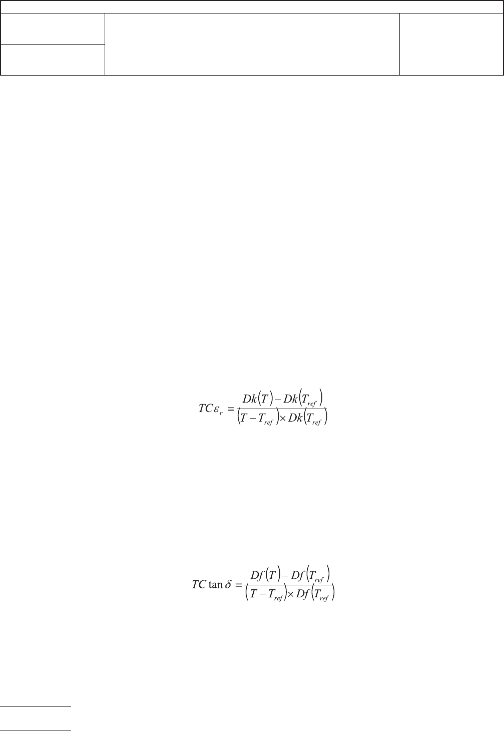
5.3.8 Thermal coefficient of relative permittivity
e
r
(short for TC
e
r
) is the change rate of relative permittivity per temperature
change. The unit of TC
e
r
is 10
-6
/°C. Generally, the relative permittivity of a specimen at its base temperature T
ref
of 23 °C
(is used as the base relative permittivity Dk(T
ref
). For temperature T, TC
e
r
shall be calculated according to Equation (3).
X 10
6
(3)
where
TC
e
r
is thermal coefficient of
e
r
, 10-
6
/°C;
T is test temperature, °C;
T
ref
is base temperature, °C;
Dk(T) is relative permittivity at temperature T;
Dk(T
ref
) is relative permittivity at temperature T
ref
.
5.3.9 The thermal coefficient of tan
d
(TC tan
d
) is the change in rate of loss tangent per temperature (every increase or decrease
1°C [1.8°F]. The unit of TC tan
d
is 10
-6
/°C. Generally, the loss tangent of specimen at base temperature T
ref
of 23 °C [73.4 °F]
is used as the base loss tangent Df(T
ref
). For temperature T, TC tan
d
is calculated according to the Equation (4).
X 10
6
(3)
where
TC tan
d
is thermal coefficient of tan
d
, ppm/°C;
T is the test temperature, °C;
T
ref
is base temperature, °C;
Df(T) is loss tangent at temperature T;
Df(T
ref
) is loss tangent at temperature T
ref
.

IPC-TM-650
Number Subject Date
Revision
Page 7 of 7
2.5.5.15 Relative Permittivity and Loss Tangent Using a 06/22
Split-Post Dielectric Resonator
N/A
5.3.10 If another test frequency is selected, change the SPDR test fixture in accordance with the test frequency. Then repeat
steps 5.3.2 through 5.3.9.
6 Report
6.1 For room temperature tests, report the following:
6.1.1 Test environment (temperature, humidity);
6.1.2 Test frequency;
6.1.3 Report the values and the average values of the relative permittivity and loss tangent at test frequency;
6.1.4 The preconditioning of the specimen;
6.1.5 Any anomalies in the test or variations from this test method.
6.2 For variable temperature tests, report the following:
6.2.1 Test temperature (T) and base temperature (T
ref
);
6.2.2 Test frequency;
6.2.3 Dk(T)and Df(T)at test temperature (T);
6.2.4 TC
e
r
and TC tan
d
;
6.2.5 Dk(T
ref
) and Df(T
ref
);
6.2.6 If more than one test temperature is necessary, report the curve diagram of the relative permittivity and loss tangent in
accordance with the temperature variation ;
6.2.7 The preconditioning of the specimen;
6.2.8 Any anomalies in the test or variations from this test method.
7 Notes
7.1 Accuracy of measurements of a sample of thickness h.
7.2 Permittivitymeasurement:Δ
e
/
e
=±[0.0015+Δh/h].
7.3 Losstangent:Δtan
d
= ±2 × 10
−5
or ±0.03 × tan
d
whichever is higher.
7.4 Clean test heads, standard materials and fixtures regularly.
7.5 To prevent damage to the test fixture because of the variable temperature tests, verify the test system regularly with a
standard reference sample. For example, single-crystal quartz is used as standard reference sample of thickness 0.4 mm.
The deviation of the relative permittivity measurement between the test result and the nominal value of the standard
reference sample shall be less than ± 0.7 %, while the deviation of the loss tangent shall be less than ± 2 × 10
−5
.

1.0
Scope
This
method describes a procedure for deter-
mining the ability of rigid insulating materials to resist break-
down parallel to laminations (or in the plane of the material)
when subjected to extremely high voltages at standard AC
power frequencies of 50-60Hz.
As for most electrical properties, values obtained on most
materials are highly dependent on the moisture content and
tests using different conditioning cannot be compared. Tests
in other mediums, e.g., air are generally impractical due to its
relatively low breakdown.
This method is based on the test technique described as
ASTM D229.
2.0
Applicable documents
ASTM D229
Standard
Method of Testing Rigid Sheet and
Plate Materials Used for Electrical Insulation
ASTM
D149
Standard
Test Method for Dielectric Breakdown
Voltage and Dielectric Strength of Solid Electrical Insulating
Materials at Commercial Power Frequencies
3.0
Test Specimens
3.1 Number
Four
specimens shall be tested. When speci-
fied, two shall be in the machine direction and two in the
transverse direction for reinforced materials.
3.2
Form
Specimens
shall be approximately 3.0 inch X 2.0
inch X thickness and shall be prepared by shearing or sawing
the specimen from the test sample. Two holes 0.188 inch in
diameter are to be drilled along the center line of the 3.0 inch
dimension and midway between the edges in the 2.0 inch
dimension, with a spacing of 1.0 inch ± .01 inch center to
center.
3.3
Location
The
specimens may be cut from any location
in the sheet (except from the outer 1.0 inch of full size sheets).
3.4
Foil Clad Material
Foil
clad material shall have all
metal cladding removed by etching and shall be thoroughly
cleaned prior to conditioning or testing.
4.0
Apparatus/Materials
4.1
High
voltage breakdown tester (generally 50KV mini-
mum) with current rating of .5KVA up to 10KV and 5KVA
above 10KV and a motorized control capable of a 500 volts/
second rate of rise.
4.2
Oil
tank filled with insulating oil
1
capable
of exceeding
the requirements of the specification.
4.3
Tapered
pin electrode fixture utilizing two American
Standard #3 pins. (Note spherical ends on the pins are per-
mitted and recommended to reduce likelihood of breakdown
in the oil.)
4.4
High
voltage test leads (leads rated in excess of machine
capacity are recommended).
4.5
Constant
temperature water bath, capable of 50°C ±
2°C, filled with distilled water.
4.6 Beaker
or pan filled with ambient temperature distilled
water.
4.7
Racks
for supporting specimens in the 50°C water bath
(with all specimen surfaces exposed).
4.8
Timer
0-60 seconds.
4.9
Lint
free paper towels.
5.0
Procedure
5.1 Preconditioning
Unless
otherwise specified the speci-
men shall be conditioned for 48 hours (+2 hours –0 hours) in
distilled water maintained at 50°C ± 2°C.
Following this step the specimen shall be immersed in ambi-
ent temperature distilled water for 30 minutes minimum, 4
hours maximum, to allow the specimens to achieve tempera-
ture equilibrium without a substantial change in moisture con-
tent.
1.
Insulating Oil: Transfer oil such as Shell Dial Ax may be used. Use of dibutyl phthalate is acceptable but it may cause failure of the adhesives used for plastic
tanks.
The
Institute for Interconnecting and Packaging Electronic Circuits
2215 Sanders Road • Northbrook, IL 60062
IPC-TM-650
TEST
METHODS MANUAL
Number
2.5.6
Subject
Dielectric
Breakdown of Rigid Printed Wiring
Material
Date
5/86
Revision
B
Originating Task Group
N/A
Material
in this Test Methods Manual was voluntarily established by Technical Committees of the IPC. This material is advisory only
and its use or adaptation is entirely voluntary. IPC disclaims all liability of any kind as to the use, application, or adaptation of this
material. Users are also wholly responsible for protecting themselves against all claims or liabilities for patent infringement.
Equipment referenced is for the convenience of the user and does not imply endorsement by the IPC.
P
age1of3
电子技术应用 www.ChinaAET.com