IPC-TM-650 EN 2022 试验方法.pdf - 第405页
Figure 3 Sample Areas Cut Away From the Board Figure 4 Sample Area Cut Out From the Board Shown in Figure 3 Figure 5 Sample Being Submerged and Cleaned in Liquid Flux-Removing Solvent Figure 6 Sample Being Cleaned With S…
5.10.2 Use low-pressure compressed or canned air to gen-
tly flush any remaining dye from under the part until no further
dye runs out.
5.10.3 Dry the sample in an oven, not to exceed 100 °C or
as appropriate for the sample. If possible, allow the part to dry
overnight at ambient conditions. Wet dye can smear during
component separation, resulting in false conclusions.
5.11 Remove the sectioned part from the oven and allow it
to cool.
5.12 Perform the pull operation to physically/mechanically
remove the part from the board.
5.12.1 Abrade the surface to allow for an improved bonding
of the structural adhesive.
Example: One way to perform this is to use a small piece of
coarse-grit sandpaper to lightly sand and roughen the part top
surface. This will remove the dried dye and will allow the top
surface to bond with the anchored tee nut.
5.12.2 Bond the tee nut to the top of the part using struc-
tural adhesive. Allow the structural adhesive to cure.
5.12.3 Use a pull-test fixture with a uniform tensile force to
separate the part from the board.
5.13 Examine the board and component for dye indications.
If necessary, gently dust with canned air or dry, filtered and
regulated compressed air to the separated part to clear away
pull debris (flakes of dye, solder mask, etc.).
5.13.1 Any fractured interface that was present will be
stained with dye. Usually, both sides are stained in a common
(mirrored) pattern.
5.14 Take photos of dyed regions and plot results as agreed
upon between the lab and the customer.
5.15 Test Report Include the following (or as agreed upon
between the lab and the customer):
• Initial visual observations (see 5.2 and 5.5)
• Dyed interface separation location
• If required, dye indication amount/percentage (acceptability
criteria to be determined between laboratory and customer)
Other items that can be included in the test report include:
• Mapping of all separation locations
6 Notes/Figures
The figures in this section are included for informational pur-
poses only. They do not depict a correct or incorrect method
for conducting this test method.
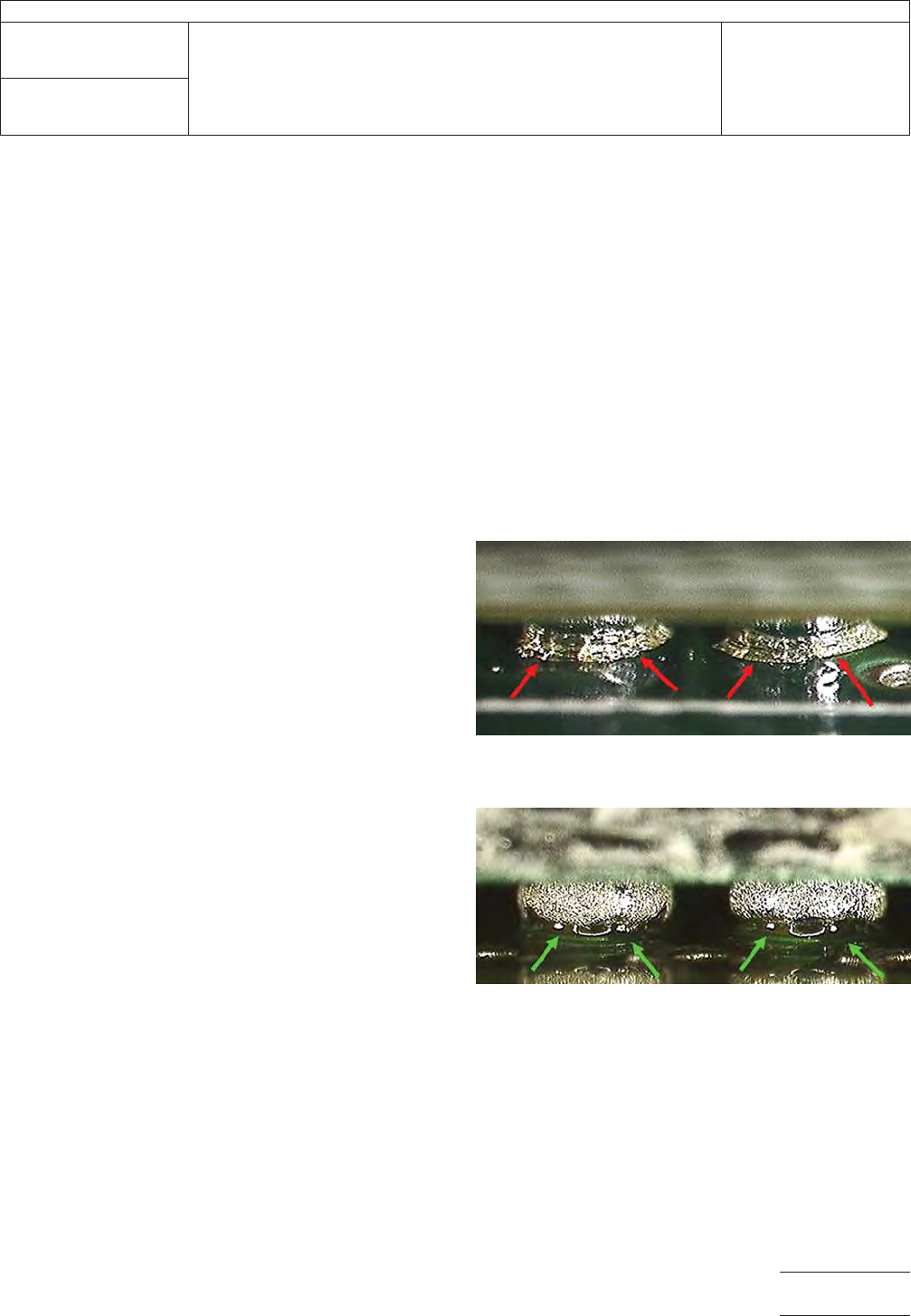
Figure 1 Ball Grid Array (BGA) With Disturbed Flux,
Indicating Possible Solder or Laminate Fractures
Figure 2 Ball Grid Array (BGA) Without Disturbed Flux
IPC-TM-650
Number
2.4.53
Subject
Dye and Pull Test Method (Formerly Known as Dye and Pry)
Date
8/2017
Revision
Page3of11
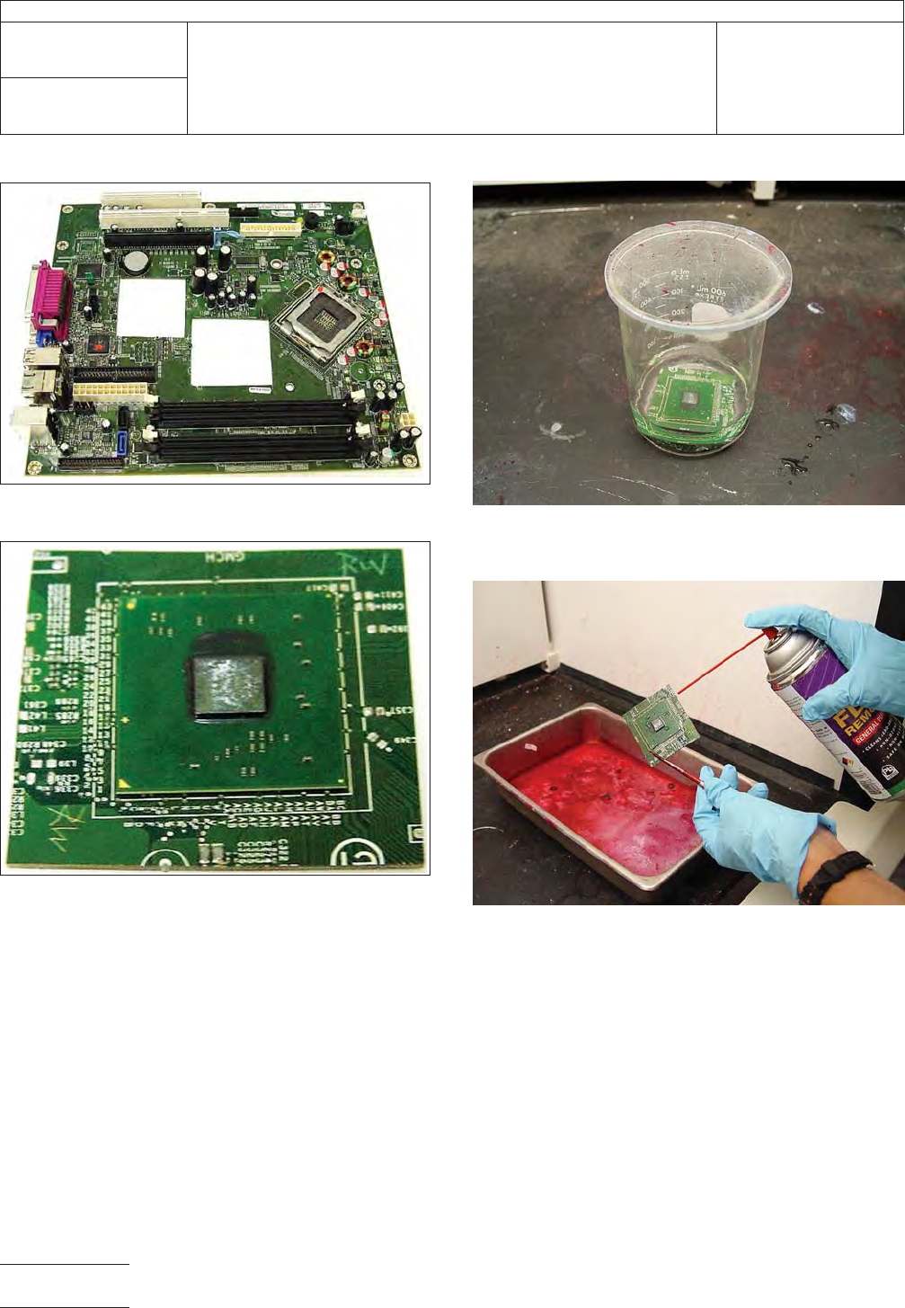
Figure 3 Sample Areas Cut Away From the Board
Figure 4 Sample Area Cut Out From the Board
Shown in Figure 3
Figure 5 Sample Being Submerged and Cleaned in
Liquid Flux-Removing Solvent
Figure 6 Sample Being Cleaned With Spray Flux
Remover After Liquid Cleaning
IPC-TM-650
Number
2.4.53
Subject
Dye and Pull Test Method (Formerly Known as Dye and Pry)
Date
8/2017
Revision
Page4of11
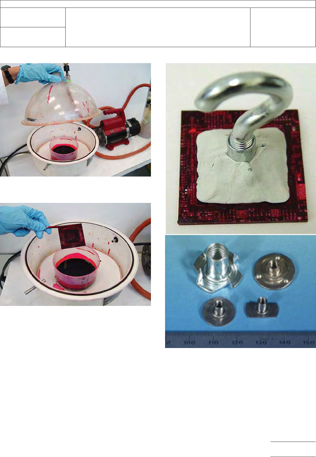
Figure 7 Dye Vacuum Station – Sample Completely
Submerged in Dye
Figure 8 Sample Being Removed From Dye
Figure 9 Sample Prepped With Tee Nut, Pull Hook
and Molding Compound (Top) and Examples of Tee
Nuts (Bottom)
Note: Sample is ready for pulling.
IPC-TM-650
Number
2.4.53
Subject
Dye and Pull Test Method (Formerly Known as Dye and Pry)
Date
8/2017
Revision
Page5of11