IPC-TM-650 EN 2022 试验方法.pdf - 第283页
1 Scope This method covers the determination of the force necessary to propagate a tear in flexible insulating mate- rials that range between the thicknesses of approx.12 µm to 100 µm [approx. 0.0005 in to 0.004 in]. Thi…
1.0
Scope
This
method is to determine the average force in
grams required to propagate tearing through a specific length
of the constant radius specimen. Because of the variation of
materials and orientation of fibers, the method has been
designed to compensate and derive acceptable data.
2.0
Applicable Documents
ASTM-D-689
Tear
Strength
3.0
Test Specimens
At
least five specimens from each
direction are required to obtain an average result. They shall
be cut as per Fig. 1. A Thwing-Albert Co. TA63 Sample Cut-
ter, Catalog No. 98 may be used.
4.0
Apparatus
A
Pendulum Impluse Tester from Thwing-
Albert Co., or equal, having: stationary clamp, moveable
clamp, stop catch, pointer and scale.
5.0
Procedure
5.1 Preparation
5.1.1
Cut
specimens, adjust and calibrate apparatus paying
particular attention to the pendulum to be certain it swings
freely.
5.1.2
Separate
clamps 0-10 in. apart and align the speci-
men in the plate perpendicular to the plane of the oscillation
of the pendulum, with the edges of the jaws gripping the
specimen in a horizontal line.
5.1.3
The
clamping surface of the jaws must be at least 1 in.
in width and 0.5 in. in depth.
5.2
Test
5.2.1
Raise
the pendulum to its top position, place speci-
men midway in the clamps so that its upper edge is parallel to
the top of the clamps and the precut initial slit is at the bottom
of and between the clamps at right angles to their top.
5.2.2
Release
the stop latch and tear the specimen.
5.2.3
As
the pendulum section completes its swing, catch it,
being careful not to disturb the position of the pointer.
5.3
Evaluation
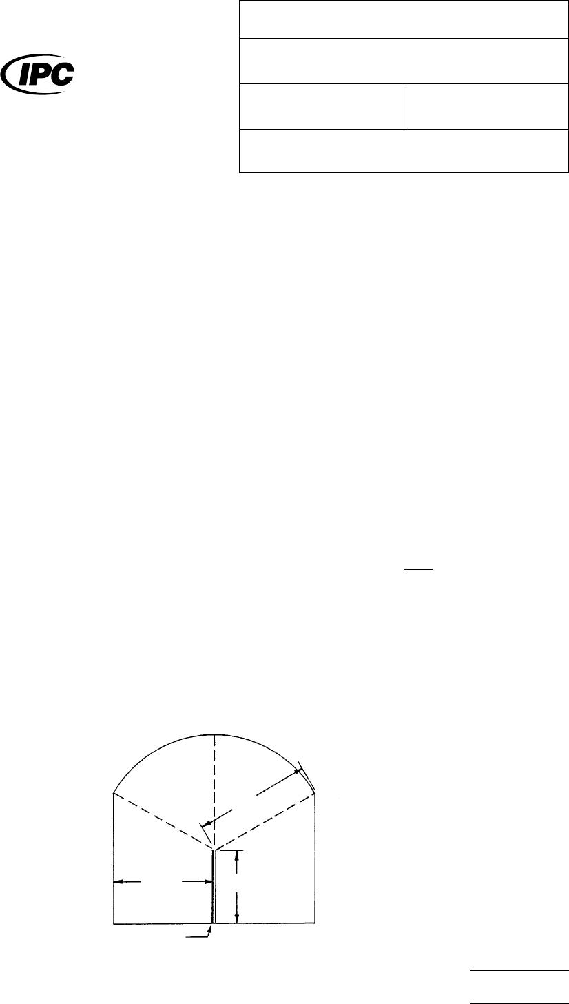
Examine
specimen carefully. If torn through
the constant-radius section within approximately 60° on either
side of the vertical line of intended tear, record the pointer
reading to the nearest 0.5 unit. If torn outside the 60°, disre-
gard specimen and test a new piece. Calculate the tearing
resistance in grams (R), as follows:
R =
SxC
n
S
= Corrected scale reading
S = Machine capacity in grams
n = Number of sheets torn
6.0 Notes Thwing-Albert
Instrument Co. is located in Phila-
delphia, Pennsylvania.
Figure
1
The
Institute for Interconnecting and Packaging Electronic Circuits
2215 Sanders Road • Northbrook, IL 60062-6135
IPC-TM-650
TEST
METHODS MANUAL
Number
2.4.17
Subject
Tear
Strength (Propagation)
Date
4/73
Revision
Originating Task Group
N/A
Material
in this Test Methods Manual was voluntarily established by Technical Committees of the IPC. This material is advisory only
and its use or adaptation is entirely voluntary. IPC disclaims all liability of any kind as to the use, application, or adaptation of this
material. Users are also wholly responsible for protecting themselves against all claims or liabilities for patent infringement.
Equipment referenced is for the convenience of the user and does not imply endorsement by the IPC.
P
age1of1
电子技术应用 www.ChinaAET.com

1 Scope This method covers the determination of the force
necessary to propagate a tear in flexible insulating mate-
rials that range between the thicknesses of approx.12 µm to
100 µm [approx. 0.0005 in to 0.004 in]. This test method is
based on ASTM D 1938.
2 Applicable Documents
ASTM D 1938
Standard Test method for Tear propagation
Resistance (Trouser Tear) of Plastic Film and Thin Sheeting by
a Single Tear Method
3 Test Specimen Preparations
3.1
If the specimens to be tested are clad flexible dielectric
materials, the copper foil shall be fully etched (removed) using
standard commercial practices. If the dielectric material to be
tested is unclad, use the material as it exists for this test
method. If the specimens are flexible insulating bonding mate-
rial that inherently has an adhesive that is not fully cured, full
curing of this adhesive shall be accomplished before the
material is tested.
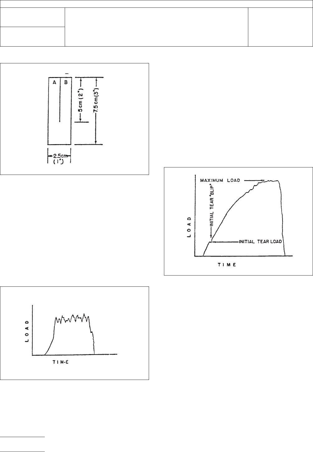
3.2 The specimens shall be of the single-tear type and
shall consist (see Figure 1) of strips 75 mm [approx. 3 in] long
by 25 mm [approx. 1 in] wide and shall have a clean longitu-
dinal slit 50 mm [approx. 2 in] long cut with a sharp razor
blade or the equivalent (Note: All dimensions shall be mea-
sured to within a 0.5% tolerance.)
3.3 If the specimen is composed of a base dielectric plus
adhesive coated on one or both sides, the thickness of the
base dielectric needs to be measured, either via cross-
sectional analysis or if feasible, removal of the adhesive lay-
er(s). The thickness of the specimen below the slit (see Figure
1) shall be measured in three places and recorded in millime-
ters or microns [in]. This provides the user of this test method
with knowledge of only the base dielectric film thickness.
3.4 Sufficient specimens shall be cut to provide a minimum
of five specimens in both transverse and longitudinal axes and
identified. Specimens shall be free of nicks or other defects
that might cause premature test failure. Verification of lack of
defects in the slit shall be done using a minimum magnifica-
tion of 3X.
4 Test Equipment
4.1 Constant Strain Rate Tensile Test Machine
This
test machine shall have a weighing head that can measure
the load applied to tear the specimen. It should be equipped
with a device for recording the load carried by the specimen
and amount of separation of the grips during the test. The
testing machine shall be essentially free from inertia lag at
the specified rate of testing and shall indicate the load with
an accuracy of ± 2% of the indicated value, or better. A
device shall be included to control the grip separation rate at
250 mm [approx.10 in] ± 5% per minute.
4.2 Thickness Measuring Devices Suitable micrometers,
or thickness gages, reading to 2.5 µm [approx. 0.10 in] or less
shall be used for measuring the thickness of the specimens.
4.3 Cutter The cutter shall be a sharp razor blade or the
equivalent.
5 Conditioning
5.1 Conditioning
Condition the specimens at 23°C ± 2°C
[73.4°F ± 3.6°F] and 50% ± 5% relative humidity for not less
than 24 hours prior to test.
5.2 Test Conditions Conduct tests in the Standard Labo-
ratory Conditions of 23°C ± 2°C [73.4°F ± 3.6°F] and 50% ±
5% relative humidity.
6 Procedure
6.1
Secure tongue A (Figure 1) in one grip and tongue B in
the other grip of the tensile testing machine using an initial grip
separation of 50 mm [approx. 2 in]. Align the specimen so that
its major axis coincides with an imaginary line joining the cen-
ters of the grips.
6.2 Using a grip separation speed of 250 mm [approx. 10 in]
/ minute, start the tensile test machine and record the load
necessary to propagate the tear through the entire unslit
25 mm [approx. l in] portion.
6.3 Test not less than five (5) specimens in each of the
transverse and longitudinal directions.
3000 Lakeside Drive, Suite 309S
Bannockburn, IL 60015-1249
IPC-TM-650
TEST METHODS MANUAL
Number
2.4.17.1
Subject
Propagation Tear Strength, Flexible Insulating
Material
Date
1/13
Revision
B
Originating Task Group
Flexible Circuits Test Methods Subcommittee
(D-15)
Material in this Test Methods Manual was voluntarily established by Technical Committees of IPC. This material is advisory only
and its use or adaptation is entirely voluntary. IPC disclaims all liability of any kind as to the use, application, or adaptation of this
material. Users are also wholly responsible for protecting themselves against all claims or liabilities for patent infringement.
Equipment referenced is for the convenience of the user and does not imply endorsement by IPC.
Page1of2
7 Calculations
7.1 Low Extensible Films
For base dielectric films that
have load-time charts characterized by Figure 2, the average
tear propagation force in grams [ounces] is obtained by aver-
aging the load indicated on the chart over the time period,
disregarding the initial and final portions of the curve. Record
the average load value reading from the tensile testing
machine. The average resistance to tearing shall be calcu-
lated from all specimens tested in each of the transverse and
longitudinal directions.
7.2 High Extensible Films For base dielectric films that
have load-time charts characterized by Figure 3, the initial
force to continue the propagation of the slit and the maximum
force attained are obtained from the chart and reported in
grams [ounces]. The initial force may be more readily detected
by placing a dot approximately 3 mm [1/8 in] in diameter at
the base of the razor blade slit with a wax pencil. As the load
is applied to the sample, the dot area is observed. When the
load is just sufficient to begin the extension of the slit, a ‘‘blip’’
is introduced on the chart (see Figure 3) by pushing the
appropriate button on the recorder or the equivalent to mark
this point. The maximum load is the highest reading on the
chart as indicated. Calculate the average of the five initial tear-
propagation forces and the average of the five maximum tear-
propagation forces in grams [ounces] for the transverse and
longitudinal directions of the material test specimens.
8 Report
8.1
Report the average base dielectric film thickness only of
the specimens tested. This provides the user of this test
method with the base dielectric film thickness only, if required,
by the flexible circuitry material specifications.
8.2 For low extensible base dielectric films described in 7.1,
report the average of the five average tear propagation deter-
minations in grams [ounces] for the transverse and longitudi-
nal specimens.
8.3 For high extensible base dielectric films described in 7.2,
report the average of the five initial tear-propagation forces
and the average of the five maximum tear-propagation forces
in grams [ounces] for the transverse and longitudinal
specimens.
IPC-24171-1
Figure 1 Single-tear specimens
IPC-24171-2
Figure 2 Load-time chart for low-extensible base
dielectric films
IPC-24171-3
Figure 3 Load-time chart for high extensible base
dielectric films
IPC-TM-650
Number
2.4.17.1
Subject
Propagation Tear Strength, Flexible Insulating Material
Date
1/13
Revision
B
Page2of2