IPC-TM-650 EN 2022 试验方法.pdf - 第334页
6.3 The glass transition for a given material will be signifi- cantly different if measured by DSC versus TMA. The test equipment used should be noted beside the glass transition valve, i.e., 136.4 °C (DSC) or 132.6 °C (…
5.3.2 Determination of Cure Factor (Delta T
g
) Cure Fac-
tor (or Delta T
g
) is the absolute difference between the glass
transition temperatures determined in the two scans, where:
Cure Factor (Delta T
g
)=T
g2
-T
g1
T
g1
=T
g
of first scan
T
g2
=T
g
of second scan
5.4 Report
5.4.1
The glass transition temperature (delta T
g
) shall be
reported for each specimen.
5.4.2 The Cure Factor shall be reported, if applicable, and
specified for each specimen.
5.4.3 The scan rate, specimen preparation, isothermal tem-
perature, hold time, and method of midpoint determination
shall be reported if other than that specified in this method.
5.4.4 The specimen size, configuration, and preparation
shall be reported.
6 Notes
6.1 Powdered Specimens
Certain materials may be more
appropriately tested using a specimen that is a powder pre-
pared by grinding or filing the sample. Consult with the equip-
ment’s instructions and with the material manufacturer for
more information.
6.2 Calibration of the instrument shall be carried out
according to the manufacturer’s instructions with at least
one standard being indium.
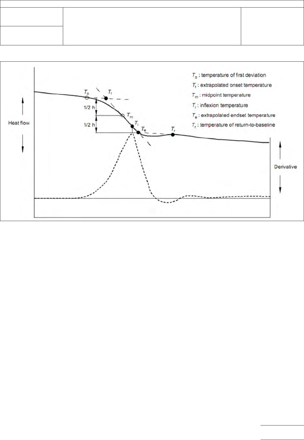
6.2.1 Computer Determination of T
g
If suitable computer
software is available, the automatic calculation of the glass
transition temperature is allowable, provided the value calcu-
lated is either the midpoint or the point of steepest deflection.
and not the onset temperature.
Calibration of the instrument must be carried out according to
the manufacturer’s instructions, with at least one standard
being indium.
Figure 1 Typical DSC Plot
IPC-TM-650
Number
2.4.25
Subject
Glass Transition Temperature and Cure Factor by DSC
Date
11/17
Revision
D
Page3of4

6.3 The glass transition for a given material will be signifi-
cantly different if measured by DSC versus TMA. The test
equipment used should be noted beside the glass transition
valve, i.e., 136.4 °C (DSC) or 132.6 °C (TMA).
6.4 Cure Factor is also described as Delta T
g
.
6.5 Testing of single-sided or unclad laminates manufac-
tured without metallic cladding on either side.
6.5.1 Single-sided or unclad laminates exhibit unreliable
Cure Factor data, due to effects of moisture and other factors.
It is recommended that Cure Factor requirements not be
applied to these laminate configurations.
6.5.2 Single-sided or unclad laminates typically exhibit T
g
approximately 8 °C to 15 °C lower than equivalent laminates
that are clad on both sides. Accordingly, the specification
requirements should take this into consideration. Reasons for
the T
g
‘‘loss’’ include presence of moisture in the release films
used in place of metallic cladding.
IPC-TM-650
Number
2.4.25
Subject
Glass Transition Temperature and Cure Factor by DSC
Date
11/17
Revision
D
Page4of4
1
Scope
This
test method shall establish and define the
methods for predicting the bond strength, on a go-no-go
basis, of additive rigid epoxy glass boards of the swell-
etchable type.
2
Applicable Documents
ASTM-D1000 Standard Test Method for Pressure-Sensitive
Adhesive-Coated Tapes Used for Electrical and Electronic
Applications
3 Test Specimen
A
minimum of two boards per test, each
board having the dimensions of 76 mm x 152 mm
4
Apparatus
4.1
Liter
beakers with slotted lids
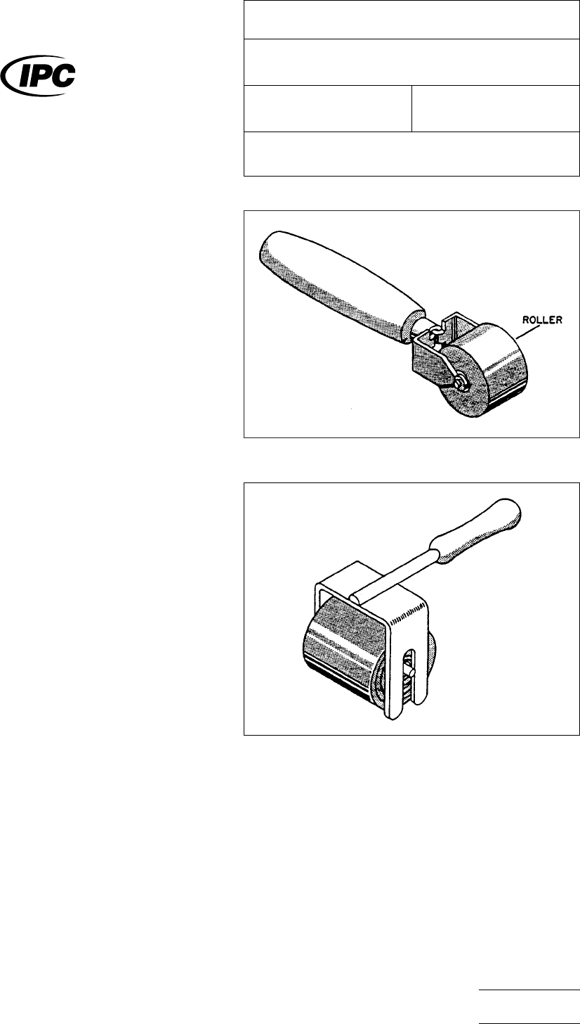
4.2
A
wooden wallpaper seam roller (see Figure 1 and Fig-
ure 2). The type in Figure 1 can be purchased in most hard-
ware shops, while the second roller is described in ASTM-
D100.
4.3
An
Instron or some other suitable peel tester, capable of
peeling at a 90° angle with a uniform, constant peel rate
4.4
3M
Brand Filament tape, No. 898, or equal. A 6.4 mm
width size is convenient.
4.5
Chemicals
An
additive chemical pre-treatment
sequence from any of the major electronic chemical suppliers
may be used. While the IPC does not endorse any specific
chemical supplier, the chemical sequence should consist of
several items.
• Conditioner
• Etchant
• Neutralizer
5
Procedure
5.1 Test
5.1.1
Prepare
the processing chemistry in one liter beakers
in accordance with the chemical suppliers’ recommendations.
5.1.2
In order to ensure that vapors from the processing
solution do not attack the resin, some precaution should be
taken to maintain minimum exposure of the untreated board
area to vapors (e.g., use of a slotted lid over beaker). Also, no
more than 10 sample boards/liter of any of the process
chemicals shall be processed.
5.1.3
Partially
submerge a board (76 mm x 152 mm) in liter
beakers following the process below. That portion of the
board, not in the liquid, provides an ‘‘as is’’ surface as a con-
trol and base comparison.
IPC-2-4-26-1
Figure
1 Paper Roller
IPC-2-4-26-2
Figure
2 Uniform Pressure Roller
The
Institute for Interconnecting and Packaging Electronic Circuits
2215 Sanders Road • Northbrook, IL 60062-6135
IPC-TM-650
TEST
METHODS MANUAL
Number
2.4.26
Subject
Tape
Test for Additive Printed Boards
Date
3/79
Revision
Originating Task Group
N/A
Material
in this Test Methods Manual was voluntarily established by Technical Committees of the IPC. This material is advisory only
and its use or adaptation is entirely voluntary. IPC disclaims all liability of any kind as to the use, application, or adaptation of this
material. Users are also wholly responsible for protecting themselves against all claims or liabilities for patent infringement.
Equipment referenced is for the convenience of the user and does not imply endorsement by the IPC.
P
age1of2
电子技术应用 www.ChinaAET.com