IPC-TM-650 EN 2022 试验方法.pdf - 第734页
1 Scope This test method describes the procedure for establishing the service temperature for metal-clad flexible base material (laminate) as described in IPC-4204 as well as cover materials and adhesive bonding films (u…
1.0
Scope
This
test method defines the procedure for
determining the low temperature flexibility of flexible printed
wiring materials by flexing while immersed in a solution mixed
from dry ice (solid carbon dioxide) and isopropyl alcohol.
2.0
Applicable Documents
None
3.0
Test Specimen
The
test specimen shall consist of an
etched conductor pattern in accordance with Figure 1.
4.0
Test Equipment
4.1
Flexing
fixture similar to Photo 1, with 1 inch diameter
mandrel.
4.2
Insulated
container, approximately 20 quart capacity.
4.3 Two lbs. dry ice (solid carbon dioxide).
4.4 Three
gallons reagent grade isopropyl alcohol.
4.5 Thermometer
capable of measuring at least -65°C.
4.6 Safety
gloves.
5.0
Procedure
5.1
Prepared
a minimum of two test specimens per Figure 1
using good commercial practices.
5.2
Prepare
a bath by mixing two lbs. of solid carbon diox-
ide with three gallons of isopropyl alcohol. Caution: use
adequate safety precautions, as bath will produce extreme
cold (approximately -65°C).
5.3
Mount
the test specimen in the test fixture such that it is
wrapped 180° around the 1 inch diameter mandrel.
5.4
Submerge
the test specimen end of the flexing fixture
into the cold bath and flex 5 times.
5.5
Remove
the specimen from the bath and examine for
cracking, delaminations, splits, and/or any other viable defect.
6.0 Notes
6.1
All
safety precautions must be exercised when working
with a mixture of dry ice and alcohol.
6.1.1
Dry
ice has a temperature of -110°F, passes directly
to the gaseous state, and is used as a refrigerant. Therefore,
it is dangerous if not handled carefully.
6.1.2
Isopropyl
alcohol is flammable and toxic; should not
be ingested, and should also be handled properly.
6.2
Detailed
drawings of the suggested flexing fixture are
available from the IPC office.
IPC-2618-1
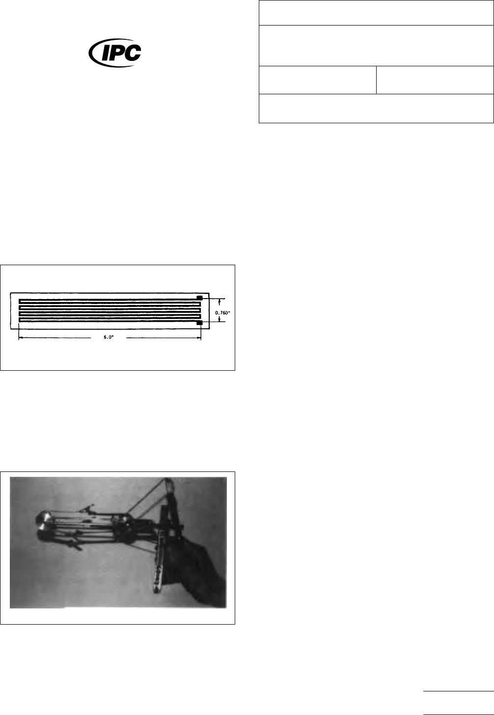
Figure
1 Low Temperature Flexibility Test Pattern. Note:
Conductors are 0.060 inch wide on 0.100 inch centers.)
IPC-2.6.18_p1
Photo
1 Low Temperature Flexibility Flexing Fixture.
(Note: Fixture Drawing available from IPC.)
The
Institute for Interconnecting and Packaging Electronic Circuits
2215 Sanders Road • Northbrook, IL 60062-6135
IPC-TM-650
TEST
METHODS MANUAL
Number
2.6.18
Subject
Low
Temperature Flexibility, Flexible Printed Wiring
Materials
Date
7/85
Revision
A
Originating Task Group
N/A
Material
in this Test Methods Manual was voluntarily established by Technical Committees of the IPC. This material is advisory only
and its use or adaptation is entirely voluntary. IPC disclaims all liability of any kind as to the use, application, or adaptation of this
material. Users are also wholly responsible for protecting themselves against all claims or liabilities for patent infringement.
Equipment referenced is for the convenience of the user and does not imply endorsement by the IPC.
P
age1of1
电子技术应用 www.ChinaAET.com

1 Scope This test method describes the procedure for
establishing the service temperature for metal-clad flexible
base material (laminate) as described in IPC-4204 as well as
cover materials and adhesive bonding films (unsupported
adhesive and supported bond plies) as described in IPC-
4203. For purposes of this test method, cover material shall
consist of coverlay and coverfilm but shall not include cover-
coat materials. Properties evaluated after thermal aging in this
test are: visual, peel strength and dielectric strength.
2 Applicable Documents
2.1 IPC
1
IPC-T-50 Terms and Definitions for Interconnecting and
Packaging Electronic Circuits
IPC-TM-650 Test Methods Manual
2
2.4.9 Peel Strength, Flexible Dielectric Materials
2.4.13 Solder Float Resistance Flexible Printed Wiring
Materials
IPC-4203 Adhesive Coated Dielectric Films for Use as Cover
Sheets for Flexible Printed Circuitry and Flexible Adhesive
Bonding Films
IPC-4562 Metal Foil for Printed Board Applications
2.2 ASTM International
3
ASTM D-149 Standard Test Method for Dielectric Break-
down Voltage and Dielectric Strength of Solid Electrical Insu-
lating Materials at Commercial Power Frequencies
3 Bond Strength Test Procedure
3.1 Specimen Preparation for Metal-Clad Flexible Base
Material (Laminate)
3.1.1
Prepare twelve specimens according to the procedure
outlined for method A of IPC TM-650, method 2.4.9, using
appropriate photolithographic processes. Etch four conduc-
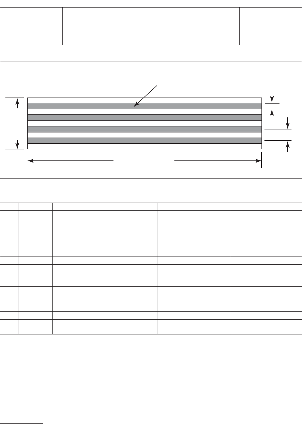
tors 3.2 mm [0.126 in] wide, 5.7 mm [0.224 in] pitch, 230 -
250 mm [9 - 10 in] long on a nominal 25 mm [1 in] wide strip
of flexible base dielectric (see Figure 1).
Single-clad or double-clad flexible base material shall be
tested in the format supplied. If the flexible base material
under test is double-clad, prepare a separate set of speci-
mens for each side. It is permissible to leave the unetched
copper on the non-test side (see Notes 6.1 and 6.2).
3.2 Specimen Preparation for Cover Material
3.2.1
Single-clad base material shall be produced from
specimens of the cover materials. Cover material shall be
bonded to the shiny side of 34.3 µm [1.35 mil] copper foil,
type CU-E1-1S or CU-E7-1S per IPC-4562 (CU-E1-1S shall
be the referee material). Copper foil cleaning shall be per the
manufacturer’s normal cleaning procedure. The referee clean-
ing procedure shall be per Table 1.
3.2.2 Prepare twelve specimens according to the procedure
outlined for method A of IPC TM-650, method 2.4.9, using
appropriate photolithographic processes. Etch four conduc-
tors 3.2 mm [0.126 in] wide, 5.7 mm [0.224 in] pitch, 230 -
250 mm [9 - 10 in] long on a nominal 25 mm [1 in] wide strip
of flexible base dielectric (see Figure 1).
3.3 Specimen Preparation for Adhesive Bonding Film
3.3.1
Metal-clad flexible base material shall be produced
from specimens of the adhesive bonding film being evaluated.
Adhesive bonding film shall be bonded to the shiny side of
34.3 µm [1350 µin] ED copper foil, type CU-E1-1S or RA
copper foil, CU-E7-1S per IPC-4562 (CU-E1-1S shall be the
referee material). Adhesive bonding film shall be bonded
between the copper foil and CU-E1-1S as support material as
illustrated in Figure 2. Copper foil cleaning shall be per the
manufacturer’s normal cleaning procedure. The referee clean-
ing procedure shall be per Table 1, the same as detailed in
IPC-4203.
Prepare specimens according to the procedure outlined for
method A of IPC TM-650, method 2.4.9, using appropriate
1. www.ipc.org
2. Current and revised IPC Test Methods are available on the IPC Web site (www.ipc.org/html/testmethods.htm)
3. www.astm.org
3000 Lakeside Drive, Suite 309S
Bannockburn, IL 60015-1249
IPC-TM-650
TEST METHODS MANUAL
Number
2.6.21
Subject
Service Temperature of Metal-Clad Flexible Laminate,
Cover Material and Adhesive Bonding Films
Date
6/11
Revision
B
Originating Task Group
Flexible Circuits Test Methods Subcommittee
(D-15)
Material in this Test Methods Manual was voluntarily established by Technical Committees of IPC. This material is advisory only
and its use or adaptation is entirely voluntary. IPC disclaims all liability of any kind as to the use, application, or adaptation of this
material. Users are also wholly responsible for protecting themselves against all claims or liabilities for patent infringement.
Equipment referenced is for the convenience of the user and does not imply endorsement by IPC.
Page1of5
photolithographic processes such that a minimum of twelve
good specimens are yielded at the end of 3.4.5. On the ‘‘Test
Surface,’’ etch four conductors 3.2 mm [0.126 in] wide,
5.7 mm [0.224 in] pitch, 230 - 250 mm [9 - 10 in] long on a
nominal 25 mm [1 in] wide strip of flexible base dielectric (see
Figures 1 and 2).
3.4 Conditioning and Aging Procedure
3.4.1
Twelve specimens, as described in section 3, shall be
subjected to a stabilization period of a minimum of 24 hours
at23°C±2°C[73.4 °F ± 3.6 °F] and 50% ± 5% RH.
IPC-2-6-21a
Figure 1 Construction of Specimens for Peel Strength Testing
Metal Conductor (4 each)
3.2 mm
[0.126 in]
25 mm [1 in]
(nom.)
230–250 mm [9–10 in]
5.7 mm
[0.224 in]
Table 1 Cleaning Process for Shiny Copper
Step Process Material Temperature Time
1 Soak Clean
Use commercially available acid or alkaline
cleaners
Per supplier recommended
temperature
Per supplier recommended
time
2 Rinse Running tap water Room Temperature 3 - 5 minutes
3 Microetch
Sodium persulfate: Two liters of deionized
water, 280 grams of sodium persulfate,
25 cc sulfuric acid
Room Temperature 1 - 2 minutes
4 Rinse Running tap water Room Temperature 1 minute
5 Acid Dip
Sulfuric acid 10% by volume, dilution 1.8
liters deionized water, 200 cc sulfuric acid
96% assay
Room Temperature 45 seconds
6 Rinse Running tap water Room Temperature 1 minute
7 Rinse Deionized water Room Temperature 1 minute
8 Dry Force air dry or blot with paper towels Room Temperature 1 - 3 minutes
9 Bake Bake in clean air-circulating oven 110±5°C[230.0 ± 9.0 °F] 10 to 15 minutes
10 Lamination
*Maximum delay between bake and
lamination shall be 30 minutes
*Lamination conditions (e.g., pressure, temperature, time, etc.) shall conform to suppliers’ recommendations.
IPC-TM-650
Number
2.6.21
Subject
Service Temperature of Metal-Clad Flexible Laminate, Cover
Material and Adhesive Bonding Films
Date
6/11
Revision
B
Page2of5