IPC-TM-650 EN 2022 试验方法.pdf - 第530页
measurement procedures. ESD control components can include static dissipative mats, deionizer systems, and opera- tor gowning. 4.4.2 Premeasurement Checks The test measurement should be performed after the completion of …
Note: Equipment drift may occur as a function of time and
environment; check with equipment manufacturer for proper
calibration frequency.
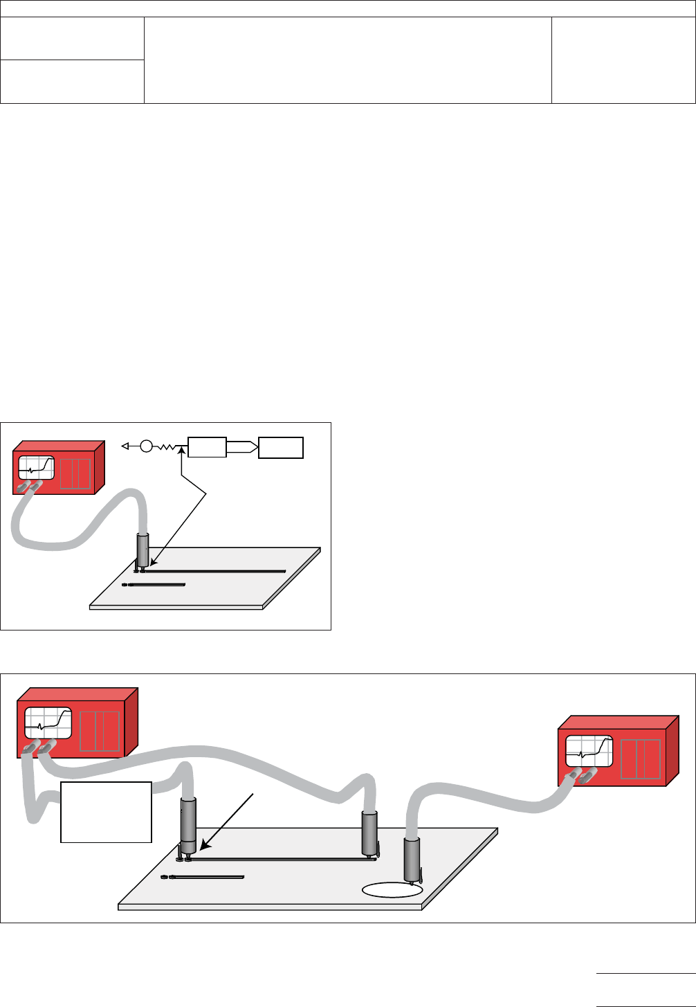
4.2 EBW, RIE, and SET2DIL Apparatus EBW, RIE, and
SET2DIL utilize a TDR measurement system which shall be
composed of a step generator, high-speed sampling oscillo-
scope, and all the necessary accessories for connecting the
TDR unit to the test specimen depicted in Figure 4-3. IPC-
2141 provides a short discussion of the TDR system architec-
ture, system considerations, and the TDR measurement
process.
4.3 SPP Apparatus SPP utilizes a TDR measurement sys-
tem with the addition of one more sampling output head and
impulse forming networks placed between the TDR Sample
head and on probe. This type of setup comprises a TDT sys-
tem as shown in Figure 4-4.
Three general probing solutions may be used. These include:
microprobes, SMA connectors, and handheld probes. Each of
these methods embodies a test structure(s) in near proximity
and on the same printed board layer.
4.4 Measurement System Requirements
4.4.1 System Calibration
Follow the TDR instrument
manufacturer’s recommendation for the frequency of factory
calibration. TDR system ‘‘field’’ checks are to be performed at
regular intervals to ensure proper operation of the test sys-
tembetween the less regular factory calibrations. Field checks
are required for the following reasons:
a) TDR instrument specifications vary with temperature.
b) TDR instrument specifications vary with time (drift).
c) TDR instrument specifications vary due to minor ESD dam-
age.
d) TDR instrument factory calibration may not include auxiliary
components (e.g., cables, probes, etc.).
TDR system field checks should also be performed after a
change of any system component (such as, cable, probes,
etc.). Ensure that the TDR instrument has been operating for
at least 30 minutes prior to any field check or test measure-
ment procedure. Use proper ESD control methods to avoid
damage to the TDR instrument in all field check and test
IPC-25512-4-3
Figure 4-3 TDR Measurement Components
IPC-25512-4-4
Figure 4-4 SPP TDT/IFF Measurement Components
TDR
Low Frequency
Impedance
Analyzer
Impulse
Forming
Network
IPC-TM-650
Number
2.5.5.12
Subject
Test Methods to Determine the Amount of Signal Loss on
Printed Boards
Date
07/12
Revision
A
Page9of24

measurement procedures. ESD control components can
include static dissipative mats, deionizer systems, and opera-
tor gowning.
4.4.2 Premeasurement Checks The test measurement
should be performed after the completion of the field check
process. Ensure that the plane of the signal line of a microstrip
(or embedded microstrip) structure is at least a distance equal
to six times the width of the microstrip signal line from any
material (such as the testing table) that can affect the dielec-
tric environment of the microstrip line. If the tests are being
conducted with hand probe(s), care must be taken to ensure
that the hands and/or arms of the operator do not contact any
surface of the printed board over the transmission line being
tested. Probes should be applied to the test points with suffi-
cient force to ensure proper electrical contact between the
conductor and the probe assembly. Consistent application
(that is, force, angle of placement, etc.) of the probes onto the
test points is important to ensure repeatable measurement
results. Before recording any measurement results, ensure
that the TDR waveform is stable (that is, not drifting in ampli-
tude or time) otherwise measurement error will occur. Ensure
that the temperature and humidity of the test environment are
within TDR instrument specifications and are stable.
4.4.3 Method for Evaluation of Measurement Repeat-
ability
Measurement repeatability is described in IPC-TM-
650, Method 1.9. This method also describes a process to
evaluate the reproducibility of a measurement system for mul-
tiple operators, on different days, and when using different
instruments. This evaluation process should be followed and
a precision-to-tolerance ratio acceptable to the customer
obtained.
4.4.4 TDR Requirements In general, the following
describes minimum TDR requirements. Improvement to these
requires agreement between customer and vendor.
4.4.4.1 EBW: TDR Requirements The voltage measure-
ment resolution of the TDR unit shall be at least 1% of the
step amplitude. Step aberrations should be ± 3% or less over
the zone 10 ns to 20 ps before step transition; +10%, -5% or
less for the first 300 ps following step transition; ±3% or less
over the zone 300 ps to 5 ns following step transition; ± 1%
or less over the zone 5 ns to 100 ns following step transition;
0.5% after 100 ns following step transition. The time base
accuracy shall be less than 2 ps.
4.4.4.2 RIE: TDR Requirements The voltage measure-
ment resolution of the TDR unit shall be within 1% of the step
amplitude. Step aberrations should be ± 3% or less over the
zone 10 ns to 20 ps before step transition; +10%, -5% or less
for the first 300 ps following step transition; ± 3% or less over
the zone 300 ps to 5 ns following step transition; ± 1% or less
over the zone 5 ns to 100 ns following step transition; 0.5%
after 100 ns following step transition. The time base accuracy
shall be less than ± 1% of full scaled used. The captured time
shall be at least twice the transit time and shall contain at
least 2000 samples. The time between samples shall also be
less than 25 ps.
4.4.4.3 SPP: TDR Requirements The voltage measure-
ment resolution of the TDR unit shall be at least 1% of the
step amplitude. Step aberrations should be ± 3% or less over
the zone 10 ns to 20 ps before step transition; +10%, -5% or
less for the first 300 ps following step transition; ± 3% or less
over the zone 300 ps to 5 ns following step transition; ± 1%
or less over the zone 5 ns to 100 ns following step transition;
0.5% after 100 ns following step transition. The time base
accuracy shall be less than 2 ps for delays less than 100 ns.
4.4.4.4 SET2DIL: TDR Requirements The voltage mea-
surement resolution of the TDR unit shall be at least 1% of
the step amplitude. Step aberrations should be ± 3% or less
over the zone 10 ns to 20 ps before step transition; +10%,
-5% or less for the first 300 ps following step transition; ± 3%
or less over the zone 300 ps to 5 ns following step transition;
± 1% or less over the zone 5 ns to 100 ns following step tran-
sition; 0.5% after 100 ns following step transition. The time
base accuracy shall be less than 1 ps.
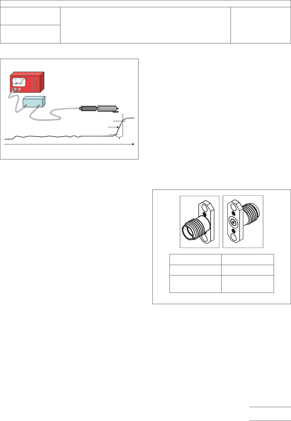
4.4.5 TDR Risetime Requirement The procedure
depicted in Figure 4-5 can be used to determine the rise time
or maximum slope of the TDR measurement system through
the probe tip. This is done to ensure that there is sufficient
high frequency content within the step pulse that is to be
injected into the device under test (DUT) for the respective test
method.
Note: The SIU is a static isolation unit designed to eliminate
static damage to the TDR sampling head. It may be included
within the TDR instrumentation.
4.4.5.1 EBW Risetime The rise time (10%-90%) for EBW
shall contain sufficient spectral content as agreed upon
between vendor and customer base on the printed board
application with the open tip of the probe. For EBW, hold the
probe in air see Figure 4-5 and measure the maximum slope
of the rise time of the step response (in Megavolts/second)
and/or the risetime. This value should be compared to the
IPC-TM-650
Number
2.5.5.12
Subject
Test Methods to Determine the Amount of Signal Loss on
Printed Boards
Date
07/12
Revision
A
Page 10 of 24
EBW requirements agreed upon between customer and ven-
dor.
4.4.5.2 RIE Risetime The rise time (10%-90%) for RIE
shall be 250 ps or as agreed upon between vendor and cus-
tomer with an open tip of the probe as illustrated in Figure 4-5.
4.4.5.3 SPP Risetime The rise time (10%-90%) for SPP
shall be 11 to 35 ps or less at the open tip of the probe or
cable connector as illustrated in Figure 4-5. SPP has an addi-
tional requirement of an impulse forming network to be
located between the TDR head and the test probe.
4.4.5.4 SET2DIL Risetime The rise time (10-90%) for
SET2DIL shall be <35 ps at the open tip of the probe or cable
connector as illustrated in Figure 4-5.
4.4.6 TDR Impedance The impedance of the TDR unit
should be 50 Ω with an impedance uncertainty less than or
equal to ± 0.5 Ω.
4.4.7 TDR System Calibration Follow the TDR instrument
manufacturer’s recommendation for the frequency of factory
calibration. Since RIE is related to the ratio of loss, field cali-
bration reverts to insuring proper results from calibration stan-
dards.
4.4.8 SPP Impulse Forming Network Requirement The
pulse width at the output of the IFN observed at the probe tip
shall be a minimum of 20 ps. The recommendation is to have
a 20 ps to 60 ps pulse width detected in TDT through the
measurement set-up on typical line lengths used in the test
coupon.
4.4.9 Printed Board Connectors The TDR cable connec-
tion shall utilize a ‘‘SMA,’’ 3.50 mm, or 2.92 mm connectors
at their measurement ports. It is recommended that cable
connections be tightened with a torque wrench to follow
specifications, unless otherwise specified by the manufacturer
of the connector or cable.
Three general probing solutions may be utilized to perform the
SPP extraction: microprobe pads, SMA connectors, and
handheld probes. Surface-mounted SMAs, as shown in Fig-
ure 4-6, are recommended for SPP. They may be either
bolted or slip-fitted into the alignment holes as explained ear-
lier. The bolt-down specification for a Molex SMA style con-
nector, part number 73251-1850, is shown in Figure 4-6.
4.4.10 TDR Cabling All test cables shall meet the follow-
ing minimum specifications:
a) Coaxial with a 50 ±1 Ω characteristic impedance
b) 2.92 mm, 3.50 mm, or SMA connectors
c) Max cable insertion loss ≤2.50 dB at 65 GHz, 50 GHz,
40 GHz, or 26.5 GHz, respectively
d) Probing insertion loss ≤0.33 dB at 65 GHz, 50 GHz,
40 GHz, or 26.5 GHz, respectively
IPC-25512-4-5
Figure 4-5 Measurement of Maximum Slope of Step
Risetime at Open End of Probe
TDR Instrument
probe
SIU
Maximum
risetime
Rise time
Time
IPC-25512-4-6
Figure 4-6 Bolt Down Torque Requirement for 2
Connector Styles
Connecter Type Required Torque
SMA 5 in-lb (0.56 N-m)
3.50 mm
2.92 mm
8 in-lb (0.90 N-m)
IPC-TM-650
Number
2.5.5.12
Subject
Test Methods to Determine the Amount of Signal Loss on
Printed Boards
Date
07/12
Revision
A
Page 11 of 24