IPC-TM-650 EN 2022 试验方法.pdf - 第389页
IPC-I-003166- Figure 1 T est apparatus for spitting test ▼ ▼ ▼ ▼ ▼ ▼ ▼ Stand Soldering Iron Metal tray to collect solder Hole 11mm Diameter 45° Metal tray Aluminum Foil Flux Cored Solder Wire IPC-TM-650 Number 2.4.48 Sub…

1.0
Scope
This
test method provides a measurement of
the spitting characteristics of flux-cored wire and ribbon sol-
der.
2.0
Applicable Documents
J-STD-006
Requirements
and Test Methods for Electronic
Grade Solder Alloys and Fluxed and Non-fluxed Solid Solders
for Electronic Soldering Applications
3.0
Test Specimen
One
five meter length of the J-STD-
006 flux-cored wire or ribbon solder (may be cut into several
smaller lengths for convenient handling).
4.0
Apparatus
4.1
One
laboratory stand with soldering iron support clamp
and metal support ring or tray with a suitable hole in center.
4.2
One
20 by 20 cm piece of aluminum foil with 11 ± 0.5
mm diameter hole in center.
4.3
One
small metal tray with suitable hole in center, for
catching molten solder running down off of the soldering iron
tip.
4.4 One
soldering iron with a clean chisel point which has
been coated with solder and wiped clean.
5.0
Test Procedure
5.1 Preparation for Test
5.1.1
Using
additional pieces of solder identical to the test
specimen, determine the flux content of the flux cored solder
in accordance with IPC-TM-650, Test Method 2.3.34.1 and
expressed in percentage units (%F).
5.1.2
Set
up test configuration as shown in figure 1. The
soldering iron should be positioned so that its tip extends
approximately 6 mm through the aluminum foil.
5.1.3 Weight
the aluminum foil (P1) and place it on the labo-
ratory stand tray/ring so that the 11 mm hole is centered
around the tip of the soldering iron.
5.1.4
Weight
the solder sample (W1).
5.1.5 Turn on soldering iron and allow the tip temperature to
stabilize.
5.2
Test
5.2.1
Apply
the solder sample to the heated soldering iron
tip approximately at an even rate, 1 cm at a time, keeping the
soldering iron tip temperature steady.
5.3
Evaluation
5.3.1
Weight
the stub(s) of the solder specimen not melted
in the test (W2).
5.3.2
Weight
the aluminum foil containing the spattered flux
(P2).
5.3.3
Calculate
the percent weight of spattered flux as fol-
lows:
Percent by weight of spattered flux =
(P2−P1)
Fx(W
1−W2)
6.0
Notes
6.1 Safety
Observe
all appropriate safety precautions.
The
Institute for Interconnecting and Packaging Electronic Circuits
2215 Sanders Road • Northbrook, IL 60062-6135
IPC-TM-650
TEST
METHODS MANUAL
Number
2.4.48
Subject
Spitting
of Flux-Cored Wire Solder
Date
1/95
Revision
Originating Task Group
Solder Alloy Task Group (5-24c)
Material
in this Test Methods Manual was voluntarily established by Technical Committees of the IPC. This material is advisory only
and its use or adaptation is entirely voluntary. IPC disclaims all liability of any kind as to the use, application, or adaptation of this
material. Users are also wholly responsible for protecting themselves against all claims or liabilities for patent infringement.
Equipment referenced is for the convenience of the user and does not imply endorsement by the IPC.
P
age1of2
电子技术应用 www.ChinaAET.com
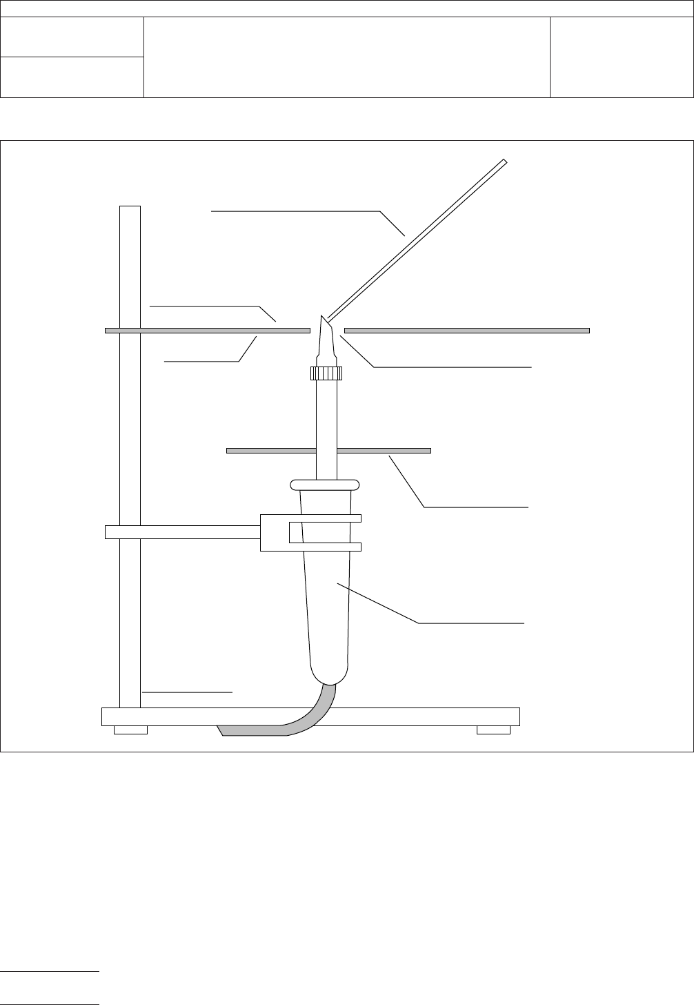
IPC-I-003166-
Figure
1 Test apparatus for spitting test
▼
▼
▼
▼
▼
▼
▼
Stand
Soldering Iron
Metal tray to
collect solder
Hole 11mm Diameter
45°
Metal tray
Aluminum Foil
Flux Cored Solder Wire
IPC-TM-650
Number
2.4.48
Subject
Spitting
of Flux-Cored Wire Solder
Date
1/95
Revision
P
age2of2
电子技术应用 www.ChinaAET.com

1.0
Scope
This
solder pool test method provides a mea-
surement of wetting characteristics of flux on/in flux-coated
and/or flux-cored solder.
2.0
Applicable Documents
J-STD-006
Requirements
and Test Methods for Electronic
Grade Solder Alloys and Fluxed and Non-fluxed Solid Solders
for Electronic Soldering Applications
ASTM
B-36
Brass
Plate, Sheet, Strip, and Rolled Bar
3.0
Test Specimen
3.1
Three
approximately 30 mm long pieces of 1.5 mm
diameter, flux-cored wire solder, three approximate 2 gram
pieces of flux-coated, flux-cored, or flux-coated and flux-
cored ribbon solder, or three approximately 2 gram quantities
of flux-coated, flux-cored, or flux-coated and flux-cored solder
preforms.
3.2
Approximately
10 ml of flux extracted and prepared in
accordance with J-STD-006, and three pieces of 1.5 mm,
non-fluxed wire solder per J-STD-006.
4.0
Apparatus and Reagents
4.1
Three
flat pieces of 0.25 mm thick 70/30 brass (per
ASTM B-36 C2600 H02) approximately 75 x 40 mm.
4.2 Degreased
steel wool #00.
4.3
Solder
pot containing not less than 4 Kg of molten sol-
der at a stabilized temperature of 60 ± 10°C above the liqui-
dus temperature of the alloy used in the solder specimens,
and having a solder surface diameter of not less than 80 mm
and a solder depth of not less than 25 mm.
4.4
Mandrel
having a diameter of 3 ± 0.5 mm.
4.5
One
pair laboratory forceps suitable for use in handling
hot brass coupons.
4.6
Timer
with a seconds display.
5.0
Test Procedure
5.1 Preparation for Test
5.1.1
Thoroughly
clean three brass coupons with steel wool
and bend one corner of each coupon up at an angle of
approximately 60° to facilitate the handling of the coupons
with forceps.
5.1.2
Preparation of Test Specimen
5.1.2.1
When
using fluxed wire or ribbon solder specimens,
individually coil each piece of the solder specimen around
mandrel and place one coiled piece in the approximate center
of each brass test coupon.
5.1.2.2
When
using fluxed solder preform specimens, place
one approximately 2 gram quantity in the approximate center
of each brass test coupon.
5.1.2.3
When
using extracted flux and non-fluxed wire sol-
der, individually coil each piece of the non-fluxed solder speci-
men around mandrel, place one drop of flux (approximately
0.05 ml) in the approximate center of each brass test coupon,
and place one coiled piece of non-fluxed solder in the center
of the flux drop on each brass test coupon.
5.2
Test
CAUTION:
When moving the brass test coupons,
take extreme care to move coupons slowly and keep their test
surface horizontal, so that the tests are not prejudiced by
movement of flux or solder unrelated to the fluxing action.
5.2.1
Scrape
the surface of the molten solder in the solder
pot to remove any dross.
5.2.2
Carefully
place one test coupon on the surface of the
molten solder, leave for 15 ± 1 second, and remove it to a flat,
level surface allowing the solder pool to solidify undisturbed.
5.2.3
Repeat
step 5.2.2 with the remaining two test
coupons.
5.3
Evaluation
5.3.1
Visually
examine the surface of the test coupons for
any evidence of flux spattering as evidenced by spots of flux
and/or flux residue outside of the main pool of solder and flux
residue.
The
Institute for Interconnecting and Packaging Electronic Circuits
2215 Sanders Road • Northbrook, IL 60062-6135
IPC-TM-650
TEST
METHODS MANUAL
Number
2.4.49
Subject
Solder
Pool Test
Date
1/95
Revision
Originating Task Group
Solder Alloy Task Group (5-24c)
Material
in this Test Methods Manual was voluntarily established by Technical Committees of the IPC. This material is advisory only
and its use or adaptation is entirely voluntary. IPC disclaims all liability of any kind as to the use, application, or adaptation of this
material. Users are also wholly responsible for protecting themselves against all claims or liabilities for patent infringement.
Equipment referenced is for the convenience of the user and does not imply endorsement by the IPC.
P
age1of2
电子技术应用 www.ChinaAET.com