IPC-TM-650 EN 2022 试验方法.pdf - 第86页
3.3 Operating Conditions. The evaluation of the plated- through holes shall be performed at room temperature (68 ° to 75 ° F) and the printed wiring boards to be evaluated shall be stabilized at that temperature for appr…
1.0
Scope
1.1
A
nondestructive inspection method for determining the
quality of plated-through connections in printed wiring boards.
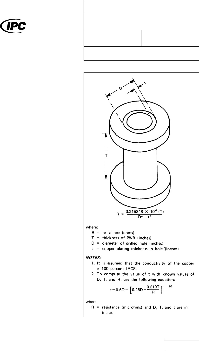
1.2 Theory. Copper will display a resistivity of known value
depending upon the geometry of the shell and the conductiv-
ity of the copper. If the shell is not uniform, defects such as
cracks, voids, or thin spots in the copper will cause the mea-
sured resistance to be higher than the theoretical value. This
value is computed by using the equation given in Fig. 1.
2.0
Applicable Documents
IPC-TC-500
Specification
for copper plated through hole,
two-sided boards, rigid.
3.0
Test Specimen
3.1 Description of Specimens.
The
following types of
specimens can be tested using the equipment specified
herein:
(1) Printed wiring boards, either two-sided or multilayer,
which can fit properly within the neck of the test meter.
NOTE:
In
testing of plated-through holes in two-sided or
multilayer printed wiring boards, the measurement is the resis-
tance of the plating in the hole only and is not related to any
interconnected circuit terminating in that hole, unless there is
an electrically parallel circuit, i.e., two or more holes located
within 0.25″ of each other.
(2) Printed wiring boards up to 3/8’’ in thickness.
(3) Plated-through connections of any diameter which can
be spanned conveniently by the probes.
3.2
Specimen Preparation.
Insulating
materials such as
flux, conformal coatings, encapsulating compounds, adhe-
sives, mold release compounds, etc., shall be removed from
the terminal areas to allow a positive metal-to-metal contact to
be made between the probes and the plated-through hole
terminal area. Closely spaced conductors shall be masked to
prevent the probes from bridging between the terminal areas
and adjacent conductors. Whatever material is used to mask
the conductors shall be located in such a manner that the
probes are not separated from the hole to be measured.
Figure
1 Resistance Calculation of Plated-Through
Connection
The
Institute for Interconnecting and Packaging Electronic Circuits
2215 Sanders Road • Northbrook, IL 60062
IPC-TM-650
TEST
METHODS MANUAL
Number
2.2.13.1
Subject
Thickness,
Plating in Holes Microhm Method
Date
1/83
Revision
A
Originating Task Group
Printed Board Test Methods Task Group (7-11d)
Material
in this Test Methods Manual was voluntarily established by Technical Committees of the IPC. This material is advisory only
and its use or adaptation is entirely voluntary. IPC disclaims all liability of any kind as to the use, application, or adaptation of this
material. Users are also wholly responsible for protecting themselves against all claims or liabilities for patent infringement.
Equipment referenced is for the convenience of the user and does not imply endorsement by the IPC.
P
age1of4
电子技术应用 www.ChinaAET.com
3.3
Operating Conditions.
The
evaluation of the plated-
through holes shall be performed at room temperature (68° to
75° F) and the printed wiring boards to be evaluated shall be
stabilized at that temperature for approximately one hour prior
to evaluation.
4.0
Apparatus
4.1 Description of Equipment.
The
microhm resistance
meter used in the nondestructive testing employs the stan-
dard four*probe technique. The equipment is portable and
suitable for bench operation. The equipment consists of two
essential parts:
(1) the mechanical portion for providing physical attachment
with the test specimen and
(2) the electrical-electronic portion for providing the microhm
readout of the through connection being measured
The probes are tension-suspended to ensure positive interfa-
cial contact with the termination areas over a range of mate-
rial thicknesses.
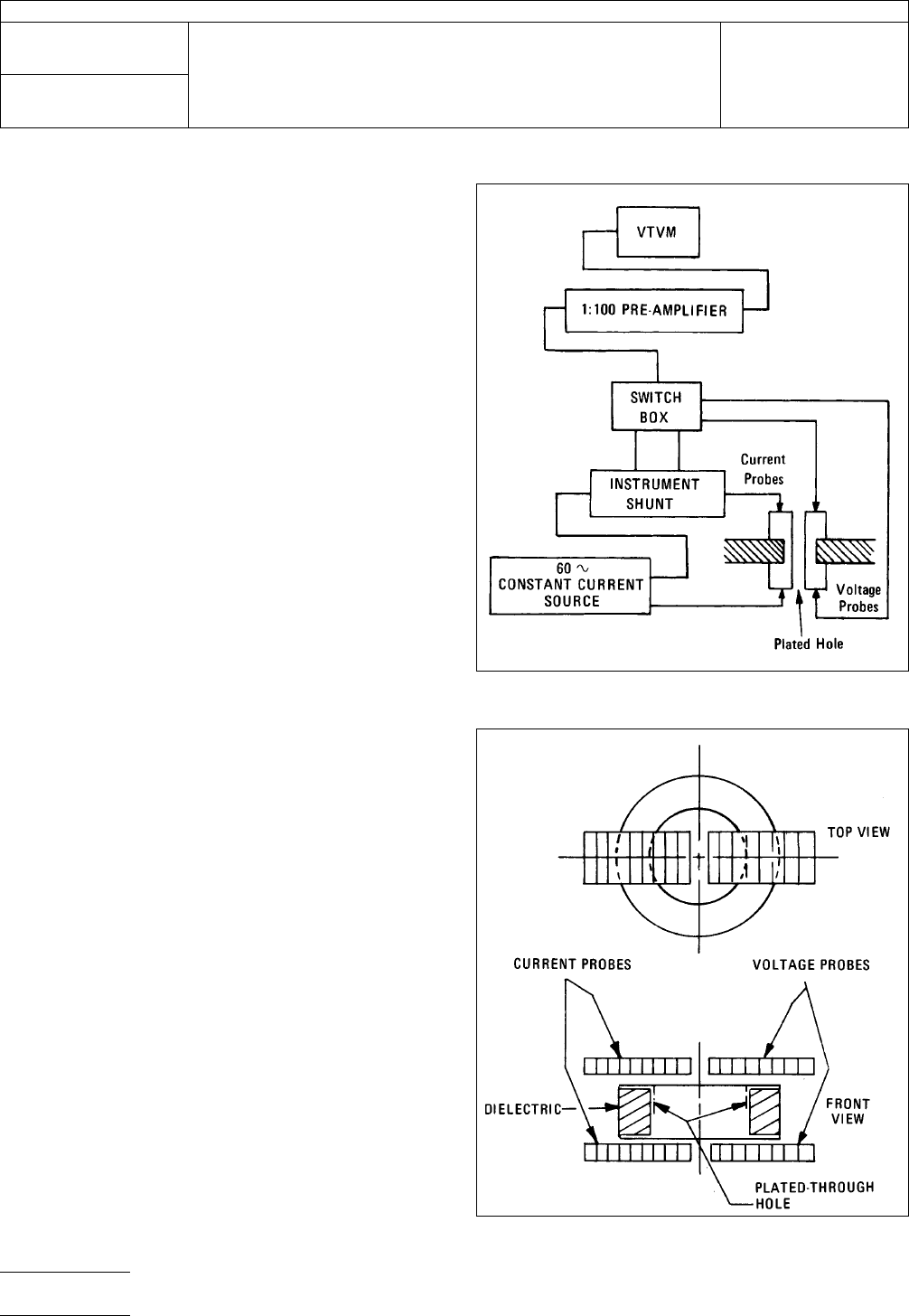
4.2
The
meter impresses a constant ac current into the
through connection, and the voltage that develops across
the, hole is sensed. This voltage is amplified and observed
visually on a suitable meter or a digitized readout. See circuit
diagram in Fig. 2A.
5.0
Procedure
5.1 Calibration of Equipment.
In
order to provide valid
resistance measurements, the equipment must be calibrated
as specified in the manufacturers’ instruction manual
5.2
Test Steps.
The
steps to be performed in evaluating
the quality of plated-through holes in printed wiring board∼ are
as follows:
5.2.1 Calibrate
the equipment.
5.2.2
Prepare
and condition the specimen(s) to be
inspected per 3.2.
5.2.3
Position
the printed wiring board between the probes
as shown in Fig. 2B.
5.2.4
Depress
the upper probes until they Awes. come
locked over the plated-through hole.
Figure
2A Circuit for Resistance Measurements
Figure
2B Ideal Probe Placement on Pad
IPC-TM-650
Number
2.2.13.1
Subject
Thickness,
Plating in Holes Microhm Method
Date
1/83
Revision
A
P
age2of4
电子技术应用 www.ChinaAET.com

NOTE:
A
steady reading indicates that the probes am mak-
ing good contact. Trial settings to obtain the minimum resis-
tance value will indicate when the probes are properly located
over the interconnection.
5.2.5
If
poor electrical contact is evidenced, relocate the
probes until a minimum resistance is indicated.
NOTE:
During the microscopic inspection (30X) of the edges
of the plated-through hole and the adjacent areas on the ter-
minal area, there shall be no detectable damage to the sur-
faces by contact with the probes during testing. In the
absence of such surface defects, the microhm testing can
assuredly be considered nondestructive.
5.2.6
Read
and record the microhm value.
5.2.7
Compare
the microhm value with the plating thickness
of the standardization curve as illustrated in Fig. 3. The theo-
retical curves shown in Fig. 3 indicate to within 0.2-rail thick-
ness the plating in the through connection and for all practical
purposes are representative of the resistance-plating thick-
ness relationships encountered in practice.
NOTE:
This
comparison shall indicate if the plating thickness
of the through connection meets the acceptable thickness
requirements
5.2.8
When
this method is used, any reading above the
specified allowable microhm reading shall be reason for fur-
ther investigation of the defect for conformance to the require-
ments of the applicable fabrication specification.
5.2.9
Plating
thickness curves shall be generated by the
user.
6.0
Resistance Curves
6.1
Curves
for the resistances of plated-through holes of
three different diameters in 1/16’’ printed wiring boards are
presented in this test method (Fig. 3). Over coatings of gold,
tin-lead, etc., can have an effect on the micro-ohm readings
depending on the electrical resistance relative to the copper.
Resistivity of tin-lead is approximately ten times that of cop-
per, while gold is of the same resistivity.
6.2
To
eliminate material and equipment variables, the user
should develop thickness-resistance curves for his particular
condition based on metallographic cross-section measure-
ments (TM-650 Method 2.2.13). These curves may be used
as guides for acceptance of product.
IPC-TM-650
Number
2.2.13.1
Subject
Thickness,
Plating in Holes Microhm Method
Date
1/83
Revision
A
P
age3of4
电子技术应用 www.ChinaAET.com