IPC-TM-650 EN 2022 试验方法.pdf - 第808页
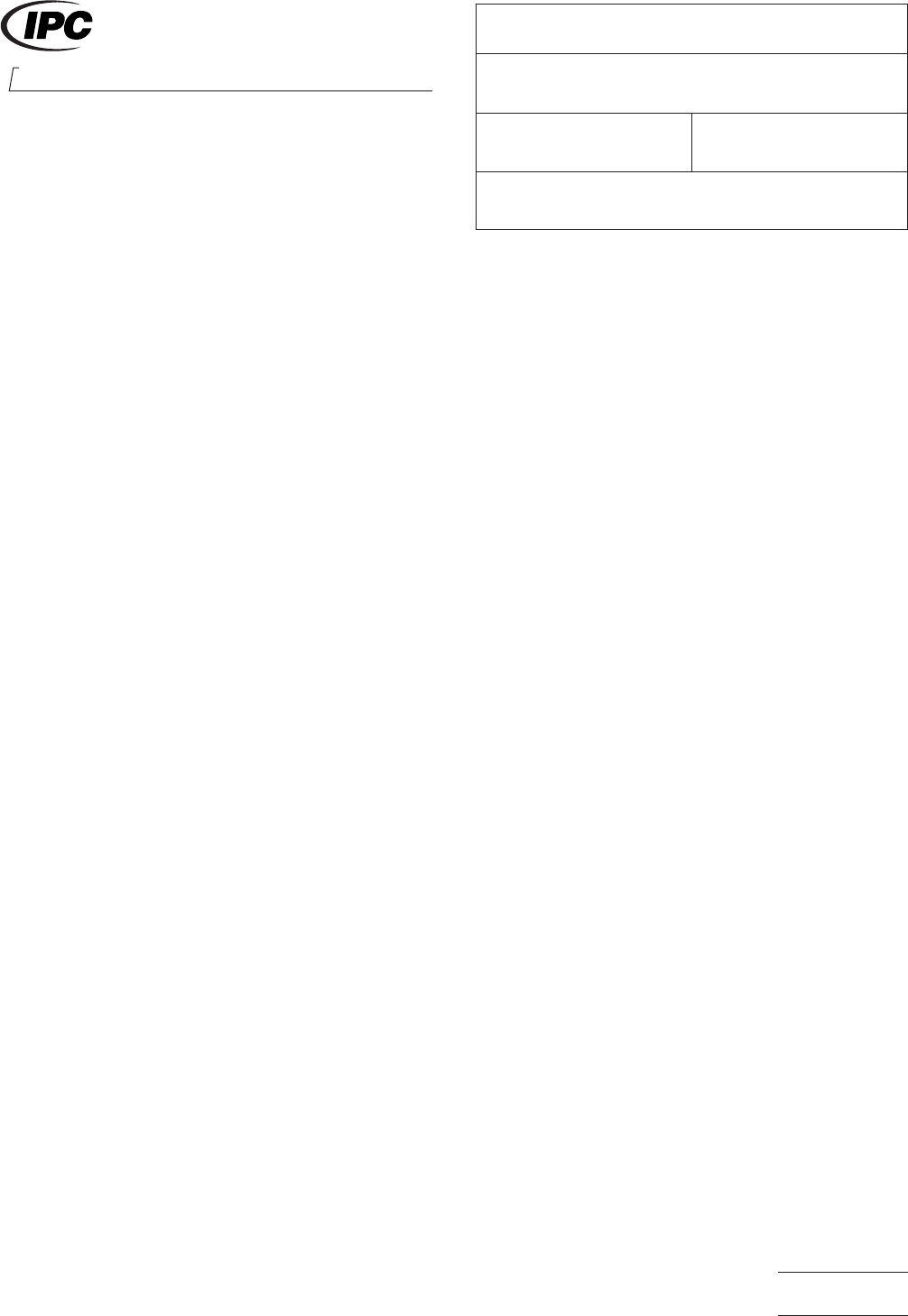
T able 1 Barometric Pressure* Altitude** In. of Mercury MM of Mercury Feet Meters 27 to 31 685 to 785 Seal Level Seal Level 17.4 442 15,000 4,572 3.44 87.4 50,000 15,240 1.40 35.6 70,000 21,336 0.35 8.9 100,000 30,480 0.…
1.0 Scope
1.1
To determine the ability of the connector to operate
safely at its rated voltage and to withstand momentary over-
potentials due to switching, surges, or other similar phenom-
ena. The dielectric withstanding voltage test is also called
high-potential, over-potential, or dielectric-strength test, but
differs from a dielectric-breakdown test as described in para-
graph 6.2.
2.0 Reference Documents
2.1
Information in this section is intended to parallel the test
method described in EIA-RS-364/TP-20.
3.0 Specimen
3.1
A plug, receptacle or mated combination as specified in
the individual connector specification.
4.0 Apparatus
4.1
High voltage source adjustable to within ± 5% of
required test voltage (DC or RMS) and capable of delivering a
minimum current of 1 milliampere.
4.2 Leakage current meter accurate to ± 5% of reading.
NOTE:
Commercial devices are available that incorporate
the voltage source and leakage monitor, as well as a fault
monitor (e.g., light, bell, automatic shut-down) into one instru-
ment.
4.3 Altitude chamber capable of maintaining a simulated alti-
tude at temperature extremes of –65°C to + 125°C.
5.0 Procedure
WARNING:
POTENTIALS USED DURING THIS TEST MAY
PROVE HAZARDOUS TO PERSONNEL. TAKE PRECAU-
TIONS TO PROTECT PERSONNEL FROM ACCIDENTAL
EXPOSURE TO THESE TEST POTENTIALS.
5.1 The withstanding voltage shall be applied between indi-
vidual pairs of immediately adjacent contacts and between the
shell and/or engaging hardware (if they exist) and the closest
individual contact(s). The method of connection of the test
voltage if significant shall be specified in the individual connec-
tor specification. When special preparations or conditions
such as special test fixtures, reconnection, or grounding iso-
lation are required, they shall be so specified.
5.2 Under the specified conditions of temperature and baro-
metric pressure, the test voltage shall be increased from zero
to the specified value as uniformly as possible at an approxi-
mate rate of 500 volts (DC or RMS) per second unless other-
wise specified.
5.3 The test voltage shall be applied for a minimum period
of 60 seconds during which time the connector under test
shall be observed for evidence of disruptive discharge or for
leakage current in excess of one (1) milliampere.
5.4 The test voltage shall be gradually reduced to zero to
avoid surges.
6.0 Notes
6.1
Acceptance criteria shall be established by the lack of
disruptive discharge as evidenced by flashover (surface dis-
charge), sparkover (air discharge), or breakdown (puncture
discharge), or of excessive leakage current. Resistance to
these conditions is an inherent characteristic of connector
geometry (e.g., contact spacing), contact configuration (e.g.,
smooth contours), and insulator materials.
6.2 Dielectric withstanding voltage shall be defined as 75
percent of the nominal dielectric breakdown voltage mea-
sured under the same conditions of altitude and temperature.
6.3 Simulated altitudes used during this test shall be
selected from those shown in Table 1.
2215 Sanders Road
Northbrook, IL 60062-6135
IPC-TM-650
TEST METHODS MANUAL
Number
3.13
Subject
Withstanding Voltage, Connectors
Date
7/75
Revision
A
Originating Task Group
N/A
Material in this Test Methods Manual was voluntarily established by Technical Committees of the IPC. This material is advisory only
and its use or adaptation is entirely voluntary. IPC disclaims all liability of any kind as to the use, application, or adaptation of this
material. Users are also wholly responsible for protecting themselves against all claims or liabilities for patent infringement.
Equipment referenced is for the convenience of the user and does not imply endorsement by the IPC.
Page1of2
ASSOCIATION CONNECTING
ELECTRONICS INDUSTRIES
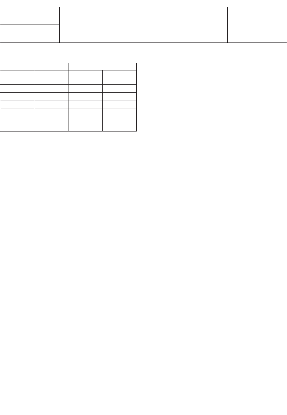
Table 1
Barometric Pressure* Altitude**
In. of
Mercury
MM of
Mercury Feet Meters
27 to 31 685 to 785 Seal Level Seal Level
17.4 442 15,000 4,572
3.44 87.4 50,000 15,240
1.40 35.6 70,000 21,336
0.35 8.9 100,000 30,480
0.045 1.14 150,000 45,720
*Source-U.S. Standard Atmosphere 1966.
**Altitude is given as a reference only and should not be specified without
barometric pressure as a test requirement.
IPC-TM-650
Number
3.13
Subject
Withstanding Voltage, Connectors
Date
7/75
Revision
A
Page2of2
1 Scope This test method is used to determine the effects
of exposure to elevated ambient temperature on the electrical
and mechanical characteristics of a connector.
2 Applicable Documents None
3 Test Specimen
3.1
A mated connector (plug and receptacle) complete with
all applicable guide, keying, and engaging hardware shall be
terminated and mounted in its normal manner during this test.
3.2 The card-edge receptacle and an applicable PCB of
minimum thickness shall be mated during this test, except as
otherwise specified.
4 Equipment/Apparatus
4.1
A suitable chamber capable of maintaining the appli-
cable temperatures within ± 20°C at the geometric center
under no load conditions. Thermal distribution shall not
exceed ± 50°C of the temperature at the geometric center.
4.2 A thermocouple bridge, potentiometer, or resistance
bridge of suitable range for the specified test conditions
5 Procedure
5.1
The chamber shall be adjusted to, and maintained at,
the temperature specified in the individual connector specifi-
cation. Thermal equilibrium shall be attained prior to the start
of the test (see 6.3).
5.2 The mated test specimen shall be suspended within the
test chamber and subjected to the specified temperature for
the required time duration called out in the individual specifi-
cation.
Note: Table 1 and Table 2 may be used as a reference for
test temperatures and test times, however, the individual con-
nector specification shall take precedence.
5.3 If groups of samples are tested, they shall be mounted
in a manner, such that the normal heat dissipation, absorp-
tion, conduction, or reflection characteristics inherent in the
connector are not infringed.
5.4 The connector test potentials, duty cycle load, and other
operating conditions during exposure shall be specified in the
applicable connector specifications
5.5 At the completion of the specified exposure time, the
conductors shall be stabilized at ambient temperature and
checked for low level circuit and insulation resistance, unless
otherwise specified in the individual connector specification.
5.6 Visual examination shall be for evidence of the following:
A. Permanent dimensional changes or distortion
B. Cracking or delamination of finishes or dielectric materials
C. Opening of seals or seams
D. Hardening or softening of dielectric materials
E. Fusing or seizure of mating connectors or components
Table 1 Test Temperatures
Test Condition Chamber Temperature (°C)
155
270
385
4 105
5 125
6 150
7 200
Table 2 Length of Test
Test Time Condition Hours
A96
B 300
C 500
D 1000
E 1500
F 2000
G 3000
H 5000
2215 Sanders Road
Northbrook, IL 60062-6135
IPC-TM-650
TEST METHODS MANUAL
Number
3.14
Subject
High Temperature Life, Connectors
Date
7/75
Revision
Originating Task Group
Material in this Test Methods Manual was voluntarily established by Technical Committees of the IPC. This material is advisory only
and its use or adaptation is entirely voluntary. IPC disclaims all liability of any kind as to the use, application, or adaptation of this
material. Users are also wholly responsible for protecting themselves against all claims or liabilities for patent infringement.
Equipment referenced is for the convenience of the user and does not imply endorsement by the IPC.
Page1of2
ASSOCIATION CONNECTING
ELECTRONICS INDUSTRIES