IPC-TM-650 EN 2022 试验方法.pdf - 第757页
IPC-2626-3-1 Figure 3-1 Method A T est Coupon IPC-2626-3-2 Figure 3-2 Method B T est Coupon IPC-TM-650 Number 2.6.26 Subject DC Current Induced Thermal Cycling Test Date 5/14 Revision A P a g e2o f1 0

1 Scope These methods determine the physical endurance
of representative coupons of printed boards to a series of high
temperature excursions from ambient. The temperature
excursions cause thermo-mechanical fatigue of the electrical
interconnect structures.
The test coupon is resistance heated by passing DC current
through the coupon to bring the temperature of the copper to
a designated temperature. Switching the current on and off
creates thermal cycles between room temperature and the
designated temperature within the sample. The laminate and
surrounding materials are heated to different extents depend-
ing on the thermal conductivity of the materials. The thermal
cycling can accelerate latent interconnect anomalies to failure.
The number of cycles achieved permits a quantitative assess-
ment of the performance.
1.1 Method A Description Method A uses a coupon with
two or more independent electrical nets. The designation for
these nets is either a power net (P) or a sense net (S). Each
electrical net consists of plated barrels and conductors (inter-
nal and external). DC current is passed through one electrical
net to heat the coupon to a designated temperature. When
the electrical net is at the designated temperature, the DC
current is turned off and cooling fans are turned on to cool the
coupons to ambient temperature. One heating and cooling
sequence represents a thermal cycle. Thermal cycling is con-
tinued to either a set number of cycles or a failure. Tempera-
ture coefficient of resistance (TCR) is estimated by proprietary
algorithms.
A failure is based on a percentage change in the bulk resis-
tance of the coupon at the designated test temperature. The
percentage change is measured independently for each elec-
trical net being tested. When the percentage change is
exceeded, the test is stopped for the coupon.
1.2 Method B Description Method B uses a coupon with
one electrical net. The net consists of via structures con-
nected by external and/or internal circuit lines in a daisy chain.
DC current is passed through the electrical net to heat the
coupon to a designated temperature. When the electrical net
is at the designated temperature, the DC current is turned off
and a cooling fan is turned on to cool the coupons to ambient
temperature. One heating and cooling sequence represents a
thermal cycle. Thermal cycling is continued to either a set
number of cycles or a failure. Temperature coefficient of resis-
tance (TCR) is measured.
A failure is based on a percentage change in the bulk resis-
tance of the coupon at the designated test temperature. The
percentage change is measured independently for each elec-
trical net being tested. When the percentage change is
exceeded, the test is stopped for the coupon.
2 Applicable Documents
2.1 IPC
1
IPC-MDP-650 Method Development Packet
IPC-TM-650 Test Methods Manual
2
2.1.1 Microsectioning
2.5.35 Capacitance of Printed Board Substrates After
Exposure to Assembly, Rework, and/or Reliability
Tests. (At the time of publication of this test method,
2.5.35 is in development.)
2.6.27 Thermal Stress, Convection Reflow Assembly
Simulation
3 Test Specimens A typical daisy chain test coupon for
each method is shown in Figure 3-1 and Figure 3-2.
1. www.ipc.org
2. Current and revised IPC Test Methods are available on the IPC Web site (www.ipc.org/html/testmethods.htm)
3000 Lakeside Drive, Suite 309S
Bannockburn, IL 60015-1249
IPC-TM-650
TEST METHODS MANUAL
Number
2.6.26
Subject
DC Current Induced Thermal Cycling Test
Date
5/14
Revision
A
Originating Task Group
PTV Reliability Test Methods (6-10c)
Material in this Test Methods Manual was voluntarily established by Technical Committees of IPC. This material is advisory only
and its use or adaptation is entirely voluntary. IPC disclaims all liability of any kind as to the use, application, or adaptation of this
material. Users are also wholly responsible for protecting themselves against all claims or liabilities for patent infringement.
Equipment referenced is for the convenience of the user and does not imply endorsement by IPC.
Page1of10
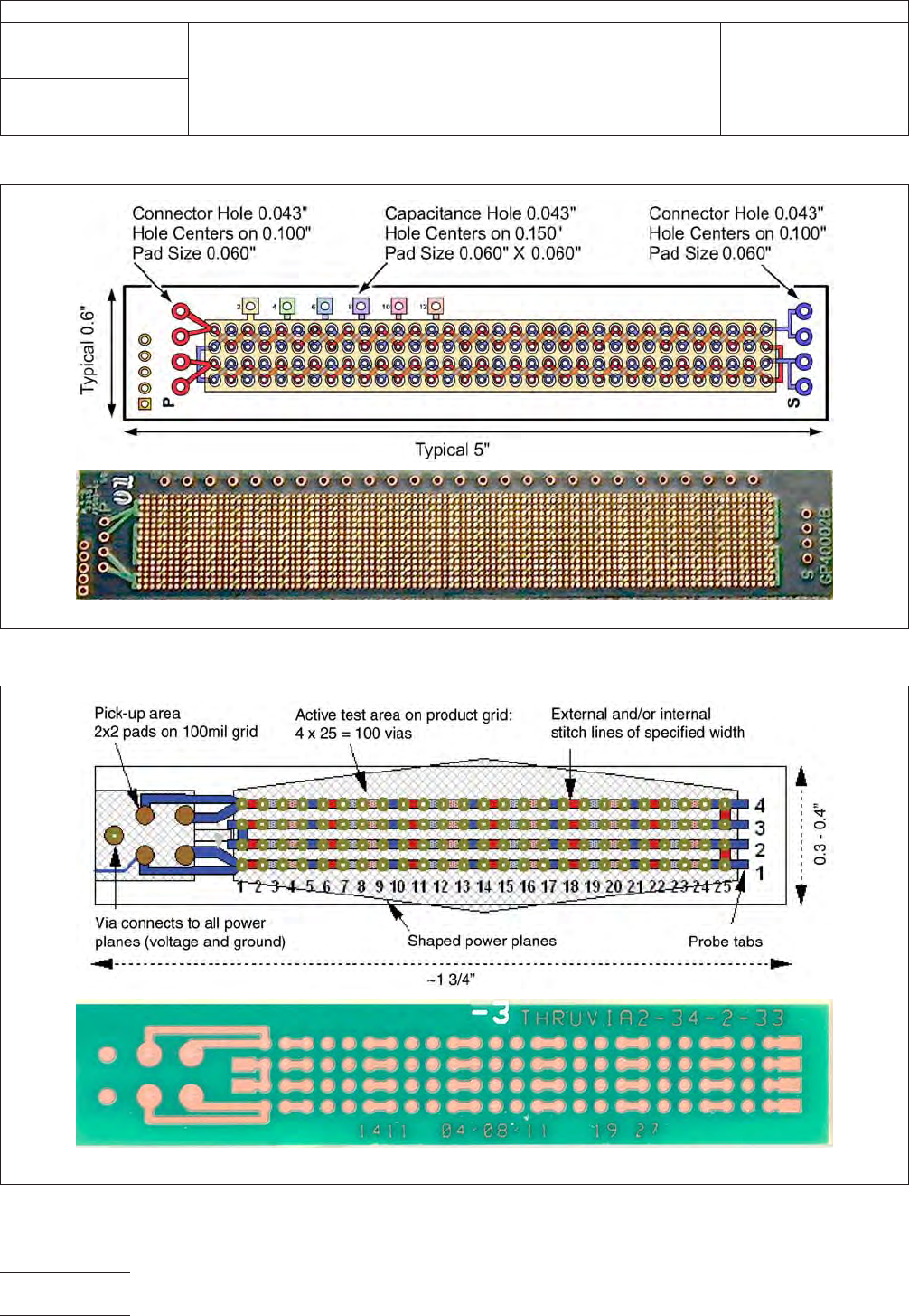
IPC-2626-3-1
Figure 3-1 Method A Test Coupon
IPC-2626-3-2
Figure 3-2 Method B Test Coupon
IPC-TM-650
Number
2.6.26
Subject
DC Current Induced Thermal Cycling Test
Date
5/14
Revision
A
Page2of10

3.1 Coupon Design Rules Certain designs rules must be
applied to achieve thermal uniformity. Electronic design files
for coupon construction are available from the equipment
supplier or printed board supplier. The resistance values (volt-
age drops) for each coupon are monitored independently for
each electrical net in test, using a four wire measurement
technique.
The test coupon(s) is incorporated on the panel to monitor or
qualify design, materials, or processes of product and/or reli-
ability assurance.
4 Apparatus or Material At the time of publication of this
test method, 4.1 and 4.2 list the only known equipment
manufacturers of this test equipment. Equivalent test systems
may be used that operate on principles similar to those iden-
tified in Method A or B. IPC encourages their submission
along with relevant validation test data. This test method will
be revised as necessary to include these test systems as this
information becomes available.
Validation of this test method was performed with the equip-
ment listed in 4.1 and 4.2. Test conditions for the validation
are provided in 6.5. If alternate test equipment is used, valida-
tion in accordance with IPC-MDP-650 and 6.5 is recom-
mended.
4.1 Method A
4.1.1
This equipment is available from:
PWB Interconnect Solutions Inc. (Canada)
URL: www.pwbcorp.com
Equipment Type: IST
4.1.2 Two (2) four-pin, 2.54 mm [0.1 in] male connector
(ITW Pancon MFSS100-4-D or equivalent).
4.1.3 Sn60Pb40, Sn63Pb37, or lead free solder.
4.1.4 Solder flux.
4.1.5 Soldering iron.
4.2 Method B
4.2.1
This equipment is available from:
i3 Electronics (USA)
(formerly Endicott Interconnect Technologies)
URL: www.i3electronics.com
Equipment Type: CITC, CITC-TCR
4.2.2 4-wire multimeter, capable of measuring milliohms
4.2.3 Thermal imaging equipment – optional
5 Procedures
5.1 Sample Selection
5.1.1
Bench top measure the resistance of each net of the
coupon with a 4-wire multimeter. A net with an open cannot
be tested. A net with a short must be reworked to test the
coupon.
5.1.2 Coupon Selection Select coupons for evaluation
based upon the test required as described in 5.1.2.1 through
5.1.2.3.
5.1.2.1 Random Sampling A sample chosen without
regard to any characteristic of the individual coupons within a
population, within one or more lots.
5.1.2.2 Selective Sampling A sample chosen based on
the resistance measurements of the sense and power nets.
Testing may include high, midrange and low resistance mea-
surements.
5.1.2.3 Comparative Sampling A sample chosen based
on the resistance measurements of the sense and power
nets. Testing should include similar resistance measurements
for the populations being tested.
5.2 Method A Procedure
5.2.1 Single Sense Testing
Solder two four-pin male con-
nectors in the 1.02 mm [0.040 in] holes at the left and right
edges of the coupon (see Figure 3-1). A solder fillet must be
apparent on both sides of the coupon.
5.2.1.1 Dual Sense Testing (Optional) When Dual Sense
Testing is required, solder three four-pin male connectors in
the 1.02 mm [0.040 in] holes at the edges of the coupon (see
Figure 5-1). A solder fillet must be apparent on both sides of
the coupon.
NOTE: Dual Sense coupons may be tested using the Single
Sense Testing method.
IPC-TM-650
Number
2.6.26
Subject
DC Current Induced Thermal Cycling Test
Date
5/14
Revision
A
Page3of10