IPC-TM-650 EN 2022 试验方法.pdf - 第697页
5.2.4 Repeat the above cycle to 100 cycles without interrup- tion. 5.2.5 Remove the specimens and allow them to reach labo- ratory conditions as specified in IPC-SM-840. 5.2.6 Evaluation Examine the specimens, on both si…
1
Scope
This
test method is to determine the physical
endurance of applied polymer solder mask to sudden
changes of high and low temperature excursions to cause
physical fatigue.
2
Applicable Documents
IPC-CC-830
Qualification
and Performance of Electrical
Insulating Compounds for Printed Board Assemblies
IPC-SM-840
Qualification
and Performance of Permanent
Coating (Solder Mask) for Printed Boards
3
Test Specimens
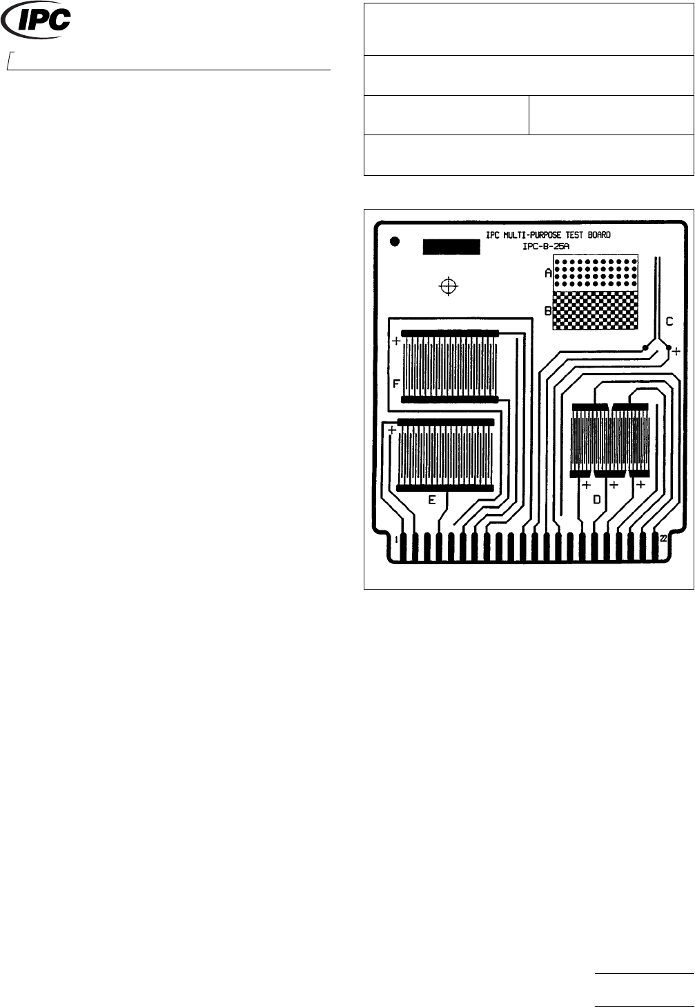
3.1 Qualification Testing
Six
IPC-B-25A test boards (see
Figure 1) coated with solder mask and cured in accordance
with solder mask supplier’s recommendations.
3.2
Conformance Testing
Six
IPC-B-25A boards (see Fig-
ure 1) containing the C pattern (‘‘Y’’ pattern) with 0.635 mm
lines/0.635 mm spacing [25.00 mil lines/25.00 mil spacing] or
minimum spacing on the production board, whichever is
smaller, coated with solder mask according to the coating
supplier’s recommendations.
4
Apparatus
4.1 Chamber
Automatically
controlled dual temperature
environmental test equipment or two separate chambers
capable of maintaining -65° ± 5°C [-85° ± 9°F] and +125° ±
5°C [+257° ± 9°F].
5
Procedure
5.1 Specimen Preparation
In
order to test the compatibil-
ity of solder mask with conformal coating, conformal coat
three of the above test specimens with a coating in accor-
dance with IPC-CC-830 and cure in accordance with the
coating supplier’s recommendations
5.2
Test
5.2.1
Place
the test specimens into the test chamber, so that
they do not touch one another, and set the parameters as fol-
lows:
a. Temperature Extremes: as specified in IPC-SM-840 ± 5°C
[± 9°F].
b. Dwell Time at Temperature Extremes: 15 minutes
c. Transfer Time: Less than two minutes
d. Number of Cycles: 100
5.2.2
Activate
the test chamber and begin testing.
5.2.3
One
thermal cycle consists of the following:
a. Expose the specimens to the high temperature for 15 min-
utes.
b. Transfer the specimens to the low temperature in less than
two minutes.
c. Expose the specimens to the low temperature for 15 min-
utes.
d. Transfer the specimens to the high temperature in less
than two minutes.
IPC-2673-1
Figure
1 IPC-B-25A Test Board
2215
Sanders Road
Northbrook, IL 60062-6135
IPC-TM-650
TEST
METHODS MANUAL
Number
2.6.7.3
(Supersedes
2.6.7.1 for Solder Mask Test)
Subject
Thermal Shock - Solder Mask
Date
07/00
Revision
Originating Task Group
Solder Mask Performance Task Group (5-33b)
Material
in this Test Methods Manual was voluntarily established by Technical Committees of IPC. This material is advisory only
and its use or adaptation is entirely voluntary. IPC disclaims all liability of any kind as to the use, application, or adaptation of this
material. Users are also wholly responsible for protecting themselves against all claims or liabilities for patent infringement.
Equipment referenced is for the convenience of the user and does not imply endorsement by IPC.
P
age1of2
ASSOCIA
TION CONNECTING
ELECTRONICS INDUSTRIES
电子技术应用 www.ChinaAET.com

5.2.4
Repeat
the above cycle to 100 cycles without interrup-
tion.
5.2.5
Remove the specimens and allow them to reach labo-
ratory conditions as specified in IPC-SM-840.
5.2.6
Evaluation
Examine the specimens, on both sides,
for all visual requirements of IPC-SM-840 using 10X magnifi-
cations (Referee of 30X magnifications).
Note: The presence of cracks in solder mask is not a suffi-
cient reason for rejection unless the conformal coating has
also cracked. Report findings and support results with the
photographs, if appropriate.
IPC-TM-650
Number
2.6.7.3
Subject
Thermal
Shock - Solder Mask
Date
07/00
Revision
P
age2of2
电子技术应用 www.ChinaAET.com

1
Scope
This
test is performed for the purpose of determin-
ing whether plated-through holes can withstand the thermo-
dynamic effects of the extreme heat to which they may be
exposed during the assembly, rework, or repair process.
2
Applicable Documents
J-STD-001
Requirements
for Soldered Electrical and Elec-
tronic Assemblies
J-STD-004
Requirements
for Soldering Fluxes
IPC-2221
Generic
standard on Printed Board Design
IPC-TM-650
Test Methods Manual
2.1.1
Microsectioning
2.1.1.2 Microsectioning – Semi or Automatic Technique
Microsection Equipment (Alternate)
3
Test Specimen
3.1
The
test specimen shall be a printed board, a portion of
a printed board or a test coupon as described in IPC-2221,
which allows for microsection evaluation of both the largest
component holes and the smallest holes on the board.
3.2
The
test specimen shall be removed from a printed
board or test coupon as specified in IPC-TM-650, Method
2.1.1 or Method 2.1.1.2, prior to precondition bake.
4
Apparatus or Material
4.1
Drying
oven capable of maintaining a uniform tempera-
ture between 121C to 149 °C [250 °F to 300 °F].
4.2
Solder
pot, electrically heated, thermostatically con-
trolled, of sufficient size, containing at least 0.9 kg of
Sn60Pb40 or Sn63Pb37 solder conforming to the contami-
nant level specified in J-STD-001.
4.3
Thermocouple
indicator or other devices to measure the
solder temperature 19 mm ± 6.4 mm [0.748 in ± 0.252 in]
below the surface.
4.4
Desiccator
with suitable desiccant.
4.5 Microscope
(100X to 200X magnification).
4.6
Stop
Watch or Timer.
4.7
Rosin
Flux, type ROL1 per J-STD-004, or flux agreed
upon between customer and vender.
4.8
Tongs.
4.9
Suitable
solvent for flux removal following the thermal
stress such as isopropyl alcohol.
5
Procedure
5.1
The
test specimen shall be conditioned by drying in an
oven for an appropriate period at 121 °C to 149 °C [250 °F to
300 °F] to remove the moisture in the specimen. For referee
purposes, a dry for a minimum of six hours at 121 °C to
149 °C [250 °F to 300 °F] shall be used. Thicker or more com-
plex specimens may require longer baking times.
5.2
Place
the test specimen in a desiccator on a ceramic
plate to cool to room temperature.
5.3
Remove
the test specimen from the desiccator using
tongs. Flux coat the surface and plated-through holes to
insure solder filling.
5.4
Verify
that the temperature of the solder (at a probe
depth of 19 mm ± 6.4 mm [0.748 in ± 0.252 in] from the sur-
face of the solder) is maintained at one of the following speci-
fied test conditions (see 6.1):
(a)
Test Condition A (default)
288
°C ± 5 °C [550 °F ± 9 °F]
(b)
Test Condition B
260
°C ± 5 °C [500 ° ± 9 °F]
(c)
Test Condition C
232
°C ± 5 °C [450 °F ± 9 °F]
5.5
Remove
the dross from the solder pot surface and lay
the test specimen on the solder for 10 seconds +1, -0 sec-
onds (see 6.2).
5.6 Using
tongs, carefully remove the test specimen from
the solder and place it on a piece of insulator to cool to room
temperature (see 6.3).
5.7
Evaluation
2215
Sanders Road
Northbrook, IL 60062-6135
IPC-TM-650
TEST
METHODS MANUAL
Number
2.6.8
Subject
Thermal
Stress, Plated-Through Holes
Date
05/04
Revision
E
Originating Task Group
Rigid Printed Board Performance Task Group
(D-33a)
Material
in this Test Methods Manual was voluntarily established by Technical Committees of IPC. This material is advisory only
and its use or adaptation is entirely voluntary. IPC disclaims all liability of any kind as to the use, application, or adaptation of this
material. Users are also wholly responsible for protecting themselves against all claims or liabilities for patent infringement.
Equipment referenced is for the convenience of the user and does not imply endorsement by IPC.
P
age1of2
ASSOCIA
TION CONNECTING
ELECTRONICS INDUSTRIES
®
电子技术应用 www.ChinaAET.com