IPC-TM-650 EN 2022 试验方法.pdf - 第614页
IPC-2-5-19-1-2 Figure 3 Cable Preparation and Cable Connection IPC-2-5-19-1-3 Figure 4 T est Cable Hookup IPC-TM-650 Number 2.5.19.1 Subject Propagation Delay of Flat Cables Using Dual Trace Oscilloscope Date 7/84 Revisi…
There
should be no time delay difference between the chan-
nels caused by the probes. If there is any delay, it should be
noted and added to the final T
D
calculation.
5.2
Prepare
the test specimen by stripping approximately 13
mm of insulation from each end of the cable. Separate the
ground and signal conductors and solder a copper buss
across the grounds (see Figure 3). The exact length of the
cable should be noted.
5.3
Solder
the termination resistor from signal lead to
ground buss at the output end of the cable.
5.4
Solder
the input resistor in series with the signal lead on
the input end of the cable (only if required).
5.5
Solder
the standard cable connection device to the test
specimen signal-to-signal lead and ground-to-ground buss.
5.6 Connect
the pulse generator to the GR to BNC adapter
via a short length of coaxial cable. Connect the input end of
test specimen to the adapter.
5.7 Connect
the oscilloscope input probes to the test speci-
men, one at the input and the other at the output termination
(see Figure 4).
5.8
Set
the oscilloscope sweep rate at 5ns/div and view
both channels on the CRT. Measure the distance between the
leading edge (at 10% pulse height) of each channel using the
display graticule as a guide (see Figure 5). Divide the result by
the cable length to get propagation delay in ns/0.3 m.
6
Notes
6.1
If
using a small sample (0.9 m), the scope should be
capable of accuracy to 1 ns/div.
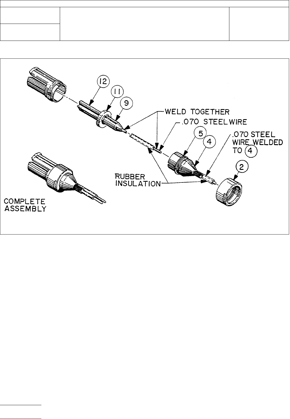
IPC-2-5-18-3
Figure
2 Cable Connection Device
IPC-TM-650
Number
2.5.19.1
Subject
Propagation
Delay of Flat Cables Using Dual Trace Oscilloscope
Date
7/84
Revision
A
P
age2of4
电子技术应用 www.ChinaAET.com
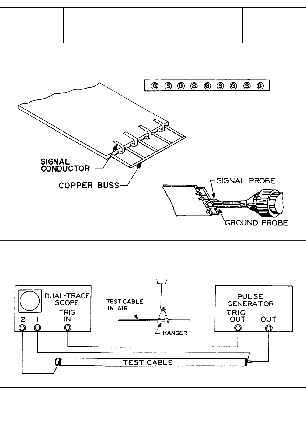
IPC-2-5-19-1-2
Figure
3 Cable Preparation and Cable Connection
IPC-2-5-19-1-3
Figure
4 Test Cable Hookup
IPC-TM-650
Number
2.5.19.1
Subject
Propagation
Delay of Flat Cables Using Dual Trace Oscilloscope
Date
7/84
Revision
A
P
age3of4
电子技术应用 www.ChinaAET.com
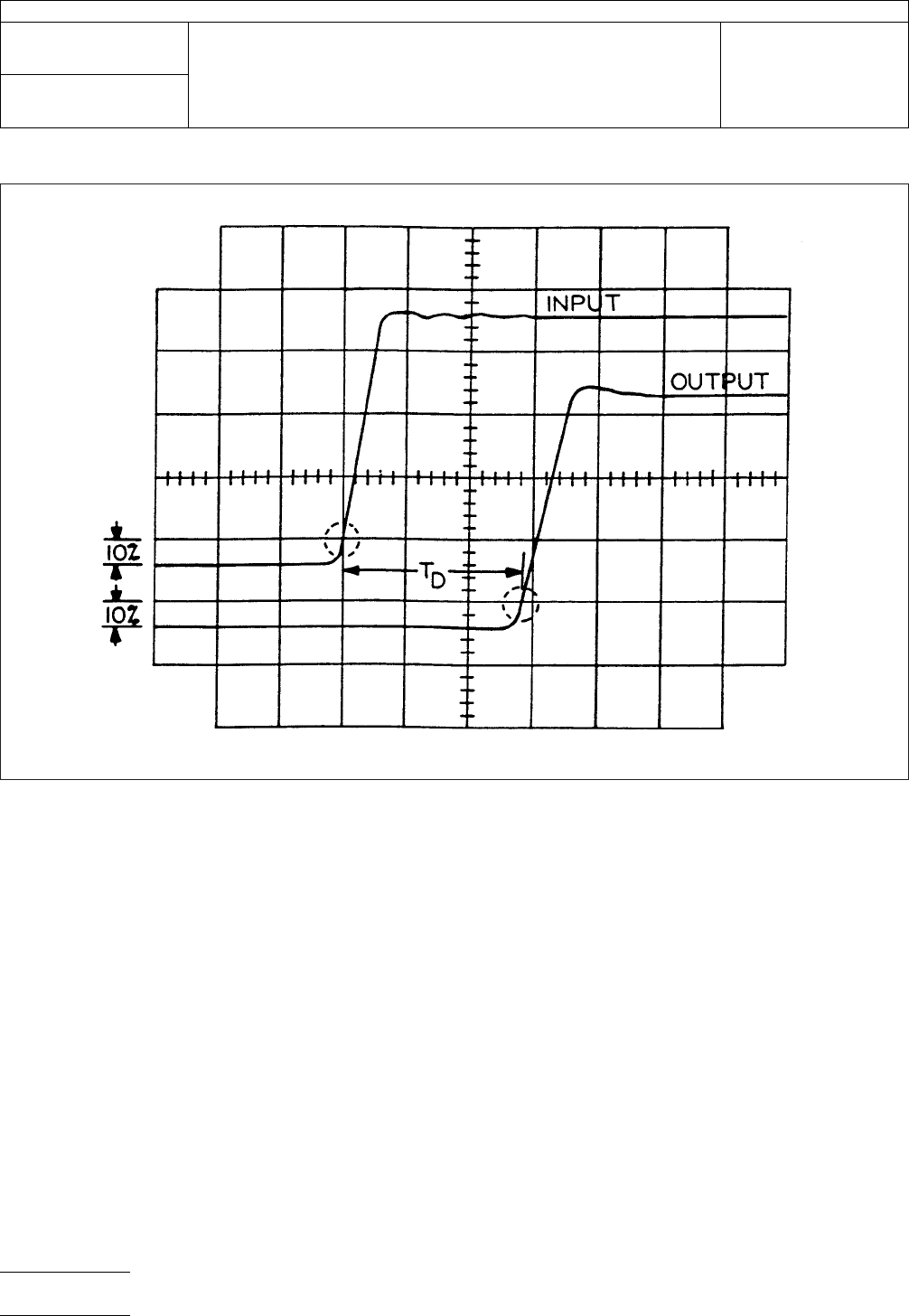
IPC-2-5-19-1-5
Figure
5 Dual Trace Oscilloscope Display
IPC-TM-650
Number
2.5.19.1
Subject
Propagation
Delay of Flat Cables Using Dual Trace Oscilloscope
Date
7/84
Revision
A
P
age4of4
电子技术应用 www.ChinaAET.com