IPC-TM-650 EN 2022 试验方法.pdf - 第391页
5.3.2 Using a suitable solvent, remove the flux residues from the three coupons sufficient to clearly see the solidified solder pool and the remaining brass coupon surface. 5.3.3 Visually examine the thickness of the sol…

1.0
Scope
This
solder pool test method provides a mea-
surement of wetting characteristics of flux on/in flux-coated
and/or flux-cored solder.
2.0
Applicable Documents
J-STD-006
Requirements
and Test Methods for Electronic
Grade Solder Alloys and Fluxed and Non-fluxed Solid Solders
for Electronic Soldering Applications
ASTM
B-36
Brass
Plate, Sheet, Strip, and Rolled Bar
3.0
Test Specimen
3.1
Three
approximately 30 mm long pieces of 1.5 mm
diameter, flux-cored wire solder, three approximate 2 gram
pieces of flux-coated, flux-cored, or flux-coated and flux-
cored ribbon solder, or three approximately 2 gram quantities
of flux-coated, flux-cored, or flux-coated and flux-cored solder
preforms.
3.2
Approximately
10 ml of flux extracted and prepared in
accordance with J-STD-006, and three pieces of 1.5 mm,
non-fluxed wire solder per J-STD-006.
4.0
Apparatus and Reagents
4.1
Three
flat pieces of 0.25 mm thick 70/30 brass (per
ASTM B-36 C2600 H02) approximately 75 x 40 mm.
4.2 Degreased
steel wool #00.
4.3
Solder
pot containing not less than 4 Kg of molten sol-
der at a stabilized temperature of 60 ± 10°C above the liqui-
dus temperature of the alloy used in the solder specimens,
and having a solder surface diameter of not less than 80 mm
and a solder depth of not less than 25 mm.
4.4
Mandrel
having a diameter of 3 ± 0.5 mm.
4.5
One
pair laboratory forceps suitable for use in handling
hot brass coupons.
4.6
Timer
with a seconds display.
5.0
Test Procedure
5.1 Preparation for Test
5.1.1
Thoroughly
clean three brass coupons with steel wool
and bend one corner of each coupon up at an angle of
approximately 60° to facilitate the handling of the coupons
with forceps.
5.1.2
Preparation of Test Specimen
5.1.2.1
When
using fluxed wire or ribbon solder specimens,
individually coil each piece of the solder specimen around
mandrel and place one coiled piece in the approximate center
of each brass test coupon.
5.1.2.2
When
using fluxed solder preform specimens, place
one approximately 2 gram quantity in the approximate center
of each brass test coupon.
5.1.2.3
When
using extracted flux and non-fluxed wire sol-
der, individually coil each piece of the non-fluxed solder speci-
men around mandrel, place one drop of flux (approximately
0.05 ml) in the approximate center of each brass test coupon,
and place one coiled piece of non-fluxed solder in the center
of the flux drop on each brass test coupon.
5.2
Test
CAUTION:
When moving the brass test coupons,
take extreme care to move coupons slowly and keep their test
surface horizontal, so that the tests are not prejudiced by
movement of flux or solder unrelated to the fluxing action.
5.2.1
Scrape
the surface of the molten solder in the solder
pot to remove any dross.
5.2.2
Carefully
place one test coupon on the surface of the
molten solder, leave for 15 ± 1 second, and remove it to a flat,
level surface allowing the solder pool to solidify undisturbed.
5.2.3
Repeat
step 5.2.2 with the remaining two test
coupons.
5.3
Evaluation
5.3.1
Visually
examine the surface of the test coupons for
any evidence of flux spattering as evidenced by spots of flux
and/or flux residue outside of the main pool of solder and flux
residue.
The
Institute for Interconnecting and Packaging Electronic Circuits
2215 Sanders Road • Northbrook, IL 60062-6135
IPC-TM-650
TEST
METHODS MANUAL
Number
2.4.49
Subject
Solder
Pool Test
Date
1/95
Revision
Originating Task Group
Solder Alloy Task Group (5-24c)
Material
in this Test Methods Manual was voluntarily established by Technical Committees of the IPC. This material is advisory only
and its use or adaptation is entirely voluntary. IPC disclaims all liability of any kind as to the use, application, or adaptation of this
material. Users are also wholly responsible for protecting themselves against all claims or liabilities for patent infringement.
Equipment referenced is for the convenience of the user and does not imply endorsement by the IPC.
P
age1of2
电子技术应用 www.ChinaAET.com

5.3.2
Using
a suitable solvent, remove the flux residues from
the three coupons sufficient to clearly see the solidified solder
pool and the remaining brass coupon surface.
5.3.3
Visually
examine the thickness of the solder pool edge
on the surface test coupons for any evidence of non-wetting
or de-wetting.
5.3.4 The
fluxed solder and/or the solder from which the flux
was extracted shall fail this solder pool test if there is any evi-
dence of non-wetting, de-wetting, or flux spattering or if the
solder pool does not feather out to a thin edge.
Note:
Irregularly
shaped solder pools do not necessarily
indicate de-wetting or non-wetting.
6.0
Safety
Observe
all appropriate safety precautions.
Consult MSDS sheets for safety precautions for chemicals
involved in this test method.
IPC-TM-650
Number
2.4.49
Subject
Solder
Pool Test
Date
1/95
Revision
P
age2of2
电子技术应用 www.ChinaAET.com
1.0
Scope
This
test method defines the procedure for
determining the Thermal Conductivity of polymer coatings on
inorganic substrates, such as polyimide on a silicon wafer.
2.0
Applicable Documents
ASTM D 2766
Standard
Test Method for Specific Heat of
Liquid and Solids
3.0
Test Specimen
See
Sample Preparation 5.1.
4.0
Apparatus
4.1
CO
2
Laser
capable of 5 Joules per pulse.
4.2
Mercury/Cadmium/Tellurium
(MCT) Infrared Detector or
equivalent.
5.0
Procedure
5.1 Sample Preparation
Samples
are prepared by form-
ing a structure on a silicon wafer consisting of 2 µm of sput-
tered carbon, 2 µm of sputtered Al metal, 25 µm of polymer
dielectric, and 2 µm of sputtered Al on wafer according to
manufacturer’s recommendations.
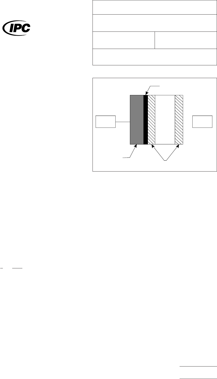
5.2
Test Procedure
Sample
is placed between the laser
and the detector according to Figure 1.
5.3
Test Analysis
Heat
rise is fit to the equation:
T = 1 −
4
π
Σ
α
n = 0
(−1)
n
2n+1
e
−{(2n+1)
2
π
2
Lt/4}
where
T is the normalized temperature rise and t is the time in
seconds and L is the fitting parameter. The thermal divusivity
k is given by:
k = (L)(l)
2
where
l is the sample thickness. The thermal condutivity, K, is
given by the equation:
K=kC
p
P
where
C
p
is
the heat capacity (as determined by ASTM D
2766) and p is the density.
2.4.50-01
Figure
1 Laser is flashed and the heat rise is measured
on the back Al by the detector
Sputtered Al
Sputtered Carbon
Polymer
Dielectri
c
Silicon
DetectorLaser
The
Institute for Interconnecting and Packaging Electronic Circuits
2215 Sanders Road • Northbrook, IL 60062-6135
IPC-TM-650
TEST
METHODS MANUAL
Number
2.4.50
Subject
Thermal
Conductivity, Polymer Films
Date
7/95
Revision
Originating Task Group
Deposited Dielectric Task Group (C-13a)
Material
in this Test Methods Manual was voluntarily established by Technical Committees of the IPC. This material is advisory only
and its use or adaptation is entirely voluntary. IPC disclaims all liability of any kind as to the use, application, or adaptation of this
material. Users are also wholly responsible for protecting themselves against all claims or liabilities for patent infringement.
Equipment referenced is for the convenience of the user and does not imply endorsement by the IPC.
P
age1of1
电子技术应用 www.ChinaAET.com