IPC-TM-650 EN 2022 试验方法.pdf - 第139页
Solder Mask Color V endor Lot Coated Thickness − Nm Min: Max: Laminate (ANSI type) Color V endor Lot Substrate Thickness − (mm) Min: Max: Solder Shock Parameters T ime (seconds) T emperature °C Check One Actual Solder Fl…
f.
Calculation of the total specimen burning time or the aver-
age specimen burning time as applicable based on 10 igni-
tions per set of five specimens (see Figure 3)
g. Calculation of the glowing time for each specimen if
required by the specification
5.6
Evaluation and Reporting
The
material shall be con-
sidered to be out of compliance with the specification if:
a. More than one specimen per set burns up to the holding
clamp on any ignition
b. More than one specimen per set burns for a period of time
longer than allowed by the specification for a single speci-
men
c. The total specimen burning time as applicable exceeds the
maximum allowed by the specification and is beyond the
tolerance specified in 5.6.2
d. More than one specimen glows for a period of time greater
than allowed by the specification (when applicable)
e. More than one specimen drips flaming particles, which
ignite the dry absorbent surgical cotton
5.6.2
Reporting
Each
test condition is reported separately.
The parameters outlined in 5.6 are to be reported only as
applicable.
5.6.3
Retests
If
only one specimen per set (five) fails to
comply with the requirements, the reserve set of specimen
shall be tested. In the case of total and/or average specimen
burning time, the reserve set shall be tested only if these cal-
culated values exceed the specification maximum by five sec-
onds or less. All specimens, their total, and their average from
the reserve set shall comply with the requirements.
6 Notes
6.1
The
inside of the burner barrel should be cleaned fre-
quently. Specimen combustion by-products can collect
around and inside the barrel tip. These deposits can be
flushed out during burner ignition and flame adjustment,
resulting in a false yellow flame tip. Proper flame adjustments
then become very difficult if allowed to remain.
6.2
When
the flame is correct and the specimen’s end is at
the proper height above the burner (9.5 mm), the inner blue
cone of the flame will just meet the end of the specimen. The
hottest area of the flame will then ignite the specimen.
6.3
Accurate
centering of the flame under the specimen is
essential for consistent test results.
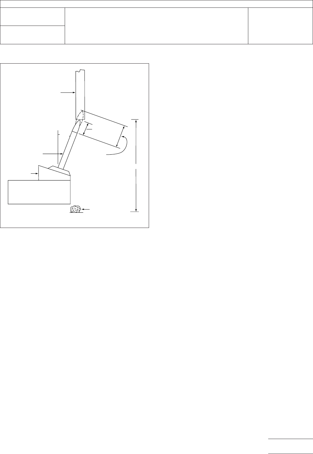
IPC-23101-2
Figure
2 Specimen Mounted in the Test Fixture
Specimen
9.5 mm
19 mm
304 mm
Dr
y absorbant
surgical cotton
Mounting
Block
Burner
20
o
IPC-TM-650
Number
2.3.10.1
Subject
Flammability
of Soldermask on Printed Wiring Laminate
Date
8/98
Revision
P
age3of4
电子技术应用 www.ChinaAET.com
Solder
Mask
Color
V
endor
Lot
Coated Thickness−Nm
Min: Max:
Laminate (ANSI type)
Color
V
endor
Lot
Substrate Thickness−(mm)
Min: Max:
Solder
Shock Parameters
Time (seconds)
T
emperature
°C
Check
One
Actual Solder
Fluidized
Alumina
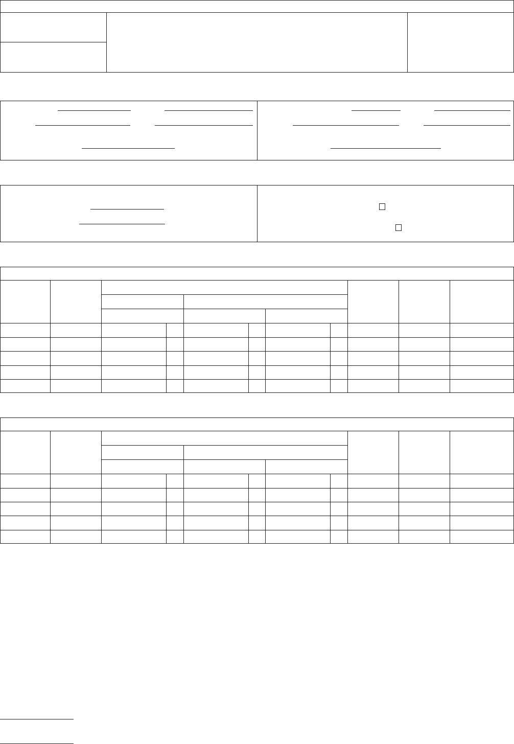
Conditioning: ≥48
Hours @ 23°C ± 2°C & 50% ± 5% RH
Specimen
Number
Total
Thickness
Time of Combustion or Combustion & Glowing
Total
Flaming
Time/ea.
Total
Flaming
& Glowing
Within (W) or
Exceeds (E)
Spec. Limits
1st Flame Appli. 2nd Flame Application
Flame (sec.) Flame (sec.) Glowing (sec.)
1
2
3
4
5
Conditioning:
168 ± 2 Hours @ 70°C ± 1°C Desiccator Cooled
Specimen
Number
Total
Thickness
Time of Combustion or Combustion & Glowing
Total
Flaming
Time/ea.
Total
Flaming
& Glowing
Within (W) or
Exceeds (E)
Spec. Limits
1st Flame Appli. 2nd Flame Application
Flame (sec.) Flame (sec.) Glowing (sec.)
1
2
3
4
5
Figure
3 Vertical Burn Flammability Data
IPC-TM-650
Number
2.3.10.1
Subject
Flammability
of Soldermask on Printed Wiring Laminate
Date
8/98
Revision
P
age4of4
电子技术应用 www.ChinaAET.com

1
Scope
The
purpose of this test method is to provide a
procedure for examining glass fabric to determine its con-
struction, including its weight, thickness, strength, and type of
weave. Since this method may be used to examine glass fab-
ric used in PCB laminate and pre-impregnated ‘‘B’’ stage
glass fabric, the method provides a procedure for removing
any obscuring resin by a combustion process.
2
Applicable Documents
IPC-EG-140
Specification
for Finished Fabric Woven from
‘‘E’’ Glass for Printed Boards
3
Test Specimen
3.1
Three
pieces of material, 5 cmx5cm
4
Equipment/Apparatus
4.1
Muffle
furnace capable of maintaining 538°C ± 14°C
4.2 Analytical
balance capable of weighing to the nearest
milligram (0.001 g)
4.3 Micrometer
capable of measuring to the nearest 0.0025
mm
4.4
Binocular
microscope, magnification to 30X
5
Procedure
5.1
A
minimum of three specimens of each test material
shall be tested by the following procedure: Place a specimen
in a crucible of suitable size and place in muffle furnace main-
tained at 538°C ± 14°C for 30 minutes. Remove from muffle
furnace and allow to cool.
5.2
Examine Residual Material
5.2.1
If
the residue shows any evidence of glass fusion,
repeat 5.1, but with the muffle furnace temperature main-
tained at 488°C ± 14°C. If there is evidence of glass fusion at
this lower temperature, again repeat the procedure of 5.1,
lowering the temperature in 50°C increments until there is no
evidence of glass fusion.
5.2.2
If
the residue shows evidence of incomplete removal
of resin, increase the temperature of the furnace by 50°C and
repeat 5.1.
5.2.3
After
the initial period and cooling to room tempera-
ture, the residual glass fabric must be white, free of resin resi-
due, and exhibit no evidence of glass fusion.
5.3
Thickness Measurement
Place
the glass fabric speci-
men between two flat plates and measure the thickness with
a micrometer. Remove the glass fabric specimen and mea-
sure the thickness of the two flat plates. The thickness of the
glass fabric shall be determined by subtracting the thickness
of the two flat plates without the glass fabric from the mea-
surement obtained with the glass fabric between the plates.
The thickness of at least three specimens shall be measured
and recorded. The thickness of each specimen shall be deter-
mined as the average of five separate measurements.
5.4
Glass Fabric Weight
5.4.1
The
length and width dimensions of the glass fabric
specimens shall be measured to the nearest 0.25 mm.
5.4.2
The
weight of the specimen shall be determined using
the analytical balance and weighing to the nearest milligram.
5.4.3
The
weight of the glass fabric shall be determined
using IPC-EG-140.
5.5
Fabric Construction
The
number of yarns in the warp
and fill used in constructing the fabric shall be determined by
counting a 2.5 sq. cm area of the fabric using a microscope.
5.6 All
other properties in Table 1 shall be as specified in the
procurement document.
5.7
Report
The
results of testing glass fabric by this test
method shall be reported in a written report, which (as a mini-
mum) contains the following:
1. Certification that the test was performed in accordance
with this test method
2. Identification of the specimens tested
3. Dimensions of each specimen (length and width)
The
Institute for Interconnecting and Packaging Electronic Circuits
2215 Sanders Road • Northbrook, IL 60062-6135
IPC-TM-650
TEST
METHODS MANUAL
Number
2.3.11
Subject
Glass
Fabric Construction
Date
4/73
Revision
Originating Task Group
N/A
Material
in this Test Methods Manual was voluntarily established by Technical Committees of the IPC. This material is advisory only
and its use or adaptation is entirely voluntary. IPC disclaims all liability of any kind as to the use, application, or adaptation of this
material. Users are also wholly responsible for protecting themselves against all claims or liabilities for patent infringement.
Equipment referenced is for the convenience of the user and does not imply endorsement by the IPC.
P
age1of3
电子技术应用 www.ChinaAET.com