IPC-TM-650 EN 2022 试验方法.pdf - 第301页
5.2 Production Testing (Twist) 5.2.1 Place the sample on the surface plate. While applying sufficient pressure to flatten the test sample, take the diagonal measurement across the sample and record it as D (see Fig- ure …
4
Equipment/Apparatus
4.1
Precision
surface plate
4.2
Thickness
measurement shims (feeler or pin gauges)
4.3
Leveling
jacks
4.4
Standard
metrology height dial indicator gauge
4.5
Gauge
blocks
4.6
Linear
measuring devices of suitable accuracy
4.7
Micrometer
of suitable accuracy for thickness measure-
ment
5
Procedure
Unless
otherwise specified, testing shall be
performed at standard laboratory conditions (see IPC-TM-
650, Section 1.3).
5.1
Production Testing (Bow)
5.1.1
Place
the sample on the surface plate. While applying
sufficient pressure to flatten the test sample, measure the
length and width of the sample and record it as length (L) &
width (W) (see Figure 3).
5.1.2
Calculate
the size of the feeler/pin gauge (Go/No-Go)
to be used for maximum bow percentage using the following
formula:
R
L
=
L (B)
100
Rw =
W (B)
100
Where:
R
L
=
Go/No-Go feeler/pin gauge size for sample length
R
W
=
Go/No-Go feeler/pin gauge size for sample width
L = Length measurement as determined above
W = Width measurement as determined above
B = Maximum allowable bow percentage
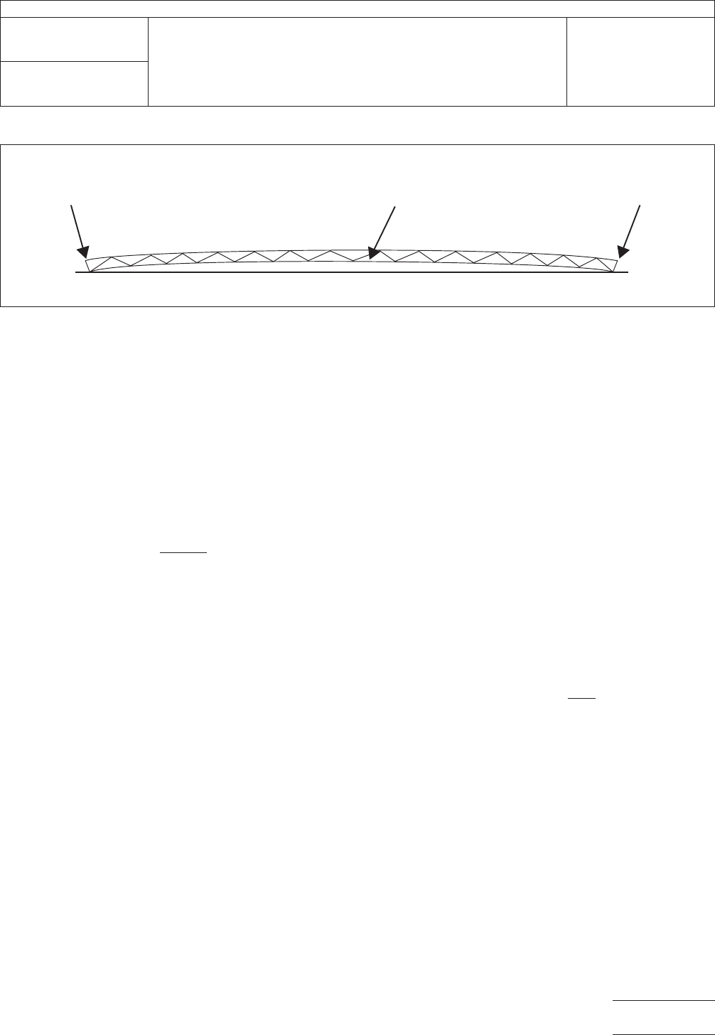
5.1.3
Place
the sample to be measured on the surface plate
with the convex of the sample facing upwards. For each edge,
apply sufficient pressure on both corners of the same sample
edge to ensure contact with the surface (see Figure 4).
5.1.4
Attempt
to slide the feeler/pin gauge of thickness R
L
under
the length side(s) of the sample and R
W
under
the width
side(s) of the sample. If the Go/No-Go feeler/pin gauge will
slide between the sample and the surface plate, the bow in
that direction exceeds the allowable percentage used in the
calculation above. Repeat this procedure until all sides of the
sample have been measured.
5.1.5
If
a determination of actual percentage of bow is
desired, repeat 5.1.1 through 5.1.4 using a feeler/pin gauge
that will easily fit between the side of the sample and the sur-
face plate. Continue to increase the feeler/pin gauge size until
the largest feeler/pin gauge that will fit between the sample
and the surface plate for both the length (x2) and width (x2) is
obtained. Measure this feeler/pin gauge with the micrometer
and record as R
L
or
R
W
.
Calculate
the percentage for bow as follows:
B
L
=
R
L
L
X
100 B
w
=
Rw
W
X
100
Where:
B
L
=
Percentage bow in the length direction
B
W
=
Percentage bow in the width direction
R
L
=
Measured maximum feeler/pin gauge size across
sample length
R
W
=
Measured maximum feeler/pin gauge size across
sample width
L = Length measurement as determined above
W = Width measurement as determined above
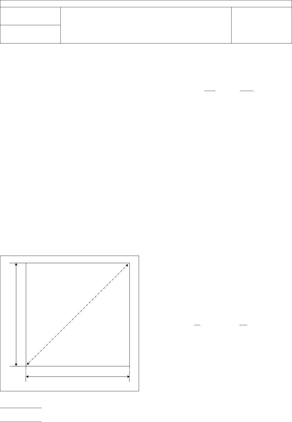
IPC-2422-3
Figure
3 External Measurements
L
D
W
IPC-TM-650
Number
2.4.22
Subject
Bow
and Twist (Percentage)
Date
6/99
Revision
C
P
age2of5
电子技术应用 www.ChinaAET.com
5.2
Production Testing (Twist)
5.2.1
Place
the sample on the surface plate. While applying
sufficient pressure to flatten the test sample, take the diagonal
measurement across the sample and record it as D (see Fig-
ure 3).
5.2.2
Calculate
the size of the feeler/pin gauge (Go/No-Go)
to be used for maximum twist percentage using the following
formula:
R =
2 (D)(T)
100
Where:
R
= Go/No-Go feeler/pin gauge size
D = Diagonal measurement across the sample as determined
above
T = Maximum allowable twist percentage
Note: This formula includes a factor of two because, by con-
straining one corner of the sample on a surface plate, the ver-
tical deflection of twist is approximately doubled.
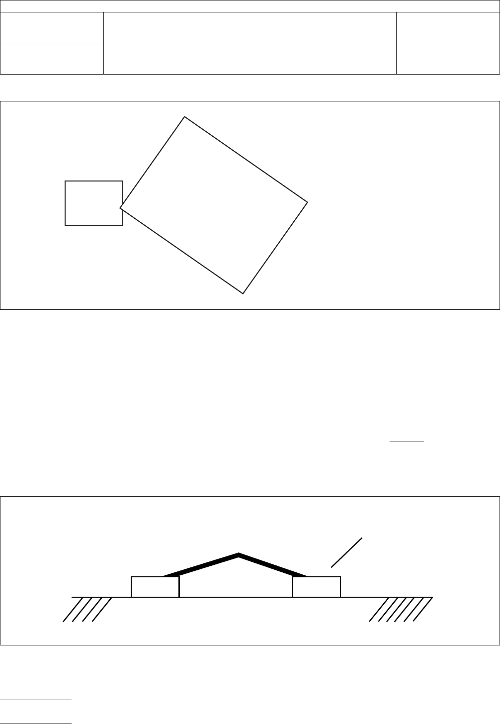
5.2.3
Place
the sample to be measured on the surface plate
with any three corners of the sample touching the surface.
Apply sufficient pressure (if necessary) to only one corner of
the sample to ensure three of the four corners are in contact
with the surface plate. It may be necessary to turn the sample
over to accomplish this (see Figure 5).
5.2.4
If
it is not possible to get three corners of the sample
to touch the surface plate by restraining only one corner, this
production test is not applicable and the referee test
described in 5.3 shall be used.
5.2.5 Attempt
to slide the feeler/pin gauge of thickness R
under the corner not touching the surface plate. If the
Go/No-Go feeler/pin gauge will slide under the corner not
touching the surface plate without lifting any of the other three
corners of the sample from the surface plate, the twist in that
direction exceeds the allowable percentage used in the calcu-
lation above. Repeat this procedure until all corners of the
sample that can be measured using this technique have been
measured.
5.2.6
If
a determination of actual percentage of twist is
desired, repeat 5.2.1 through 5.2.5 using a feeler/pin gauge
that will easily fit under the corner that is not touching the sur-
face plate. Continue to increase the feeler/pin gauge size until
the largest feeler/pin gauge size that does not lift any of the
three touching corners from the surface plate is obtained.
Measure this feeler/pin gauge with the micrometer and record
as R.
5.2.7
Calculate
the percentage of twist as follows:
Percentage Twist =
R
2 (D)
X
100
Where:
R = Go/No-Go feeler/pin gauge size
D = Diagonal measurement across the sample as determined
above
Note: This formula includes a factor of two because, by con-
straining one corner of the sample, the vertical deflection of
twist is approximately doubled.
5.3
Referee Method (Twist)
5.3.1
Place
the sample to be measured on the datum sur-
face with the two lower opposite corners touching the datum
surface or on a raised parallel surface of equal height from the
datum surface (see Figure 6).
IPC-2422-4
Figure
4 Bow Measurement
T
ouching Datum
Surface
HIGHEST POINT
measured as R or R
L
W
Touching Datum
Surface
IPC-TM-650
Number
2.4.22
Subject
Bow
and Twist (Percentage)
Date
6/99
Revision
C
P
age3of5
电子技术应用 www.ChinaAET.com
5.3.2
Support
the other two corners with leveling jacks or
some other appropriate devices, ensuring the two raised cor-
ners are of equal height from the datum surface. This may be
checked by using the dial indicator (see Figure 7).
5.3.3
Using
the dial indicator, measure the highest raised
portion on the board and record the reading as R1 (see Fig-
ure 8).
5.3.4
Without
disturbing the sample, take a reading with the
dial indicator on one of the corners contacting the surface (R2)
and record the reading (see Figure 8).
5.3.5
Take
the diagonal measurement of the sample and
record the reading.
5.3.6
Calculation
Deduct
the measured R2 from the mea-
surement R1. This difference is denoted as twist. Divide the
measured deviation by the recorded length and multiply by
100. The result of this calculation is the percentage of twist.
Percentage Twist =
R1 − R2
L
X
100
6 Notes
None
IPC-4442-5
Figure
5 Measurement of Twist
R
A
C
D
B
R = Highest
P
oint of Board
Shim under raised
corner of A.
B, C, and D touching
Datum Surface. Only
one corner may be
physically restrained.
IPC-2422-6
Figure
6 Sample Placement
▼
R2 Lowest
Corners
R2
R2
R1
Raised Parallel
Surfaces
IPC-TM-650
Number
2.4.22
Subject
Bow
and Twist (Percentage)
Date
6/99
Revision
C
P
age4of5
电子技术应用 www.ChinaAET.com