IPC-TM-650 EN 2022 试验方法.pdf - 第109页
NIST Certified Standards 5.5 The test settings used for measuring the metallic foil samples shall be the same as used for measuring the NIST- certified standards. 6 Measurement Parameters and Machine setup 6.1 All measur…

1 Purpose This procedure establishes proper methods and
practices for quantifying the surface topography/texture of
metallic foil using a noncontact, optical or laser, 3-D surface
measurement device. The primary reported values will include
Sa, Sq and Sz (see 6.3 for further information on these param-
eters) where S values are 3-D measures.
2 Applicable Documents
2.1 IPC
1
IPC-4562 Metal Foil for Printed Board Applications
2.2 International Standards
2
ISO 16610 Geometrical Product Specifications (GPS) –
Filtration
ISO 25178-2 Surface Texture: Areal – Part 2: Terms, Defini-
tions and Surface Texture Parameters
3 Metallic Foil Sample Preparation
3.1
The samples tested will be a single-layer material taken
from a representative location of metallic foil. The size of the
physical sample will be determined based on the easiest
method for obtaining a representative sample, but should be
no larger than 50 mm x 50 mm [nominally 2 in x 2 in]. Opera-
tors of the measurement tool will orient the sample so the
measurements are across the machine direction of the foil
sample or the surface of the Physical NIST Traceable
Standards.
3.2 The samples will be tested as received, but proper care
must be taken to prevent scratches, dents or bending to
insure the integrity of the surface. Operators of the measure-
ment tool will orient the sample so that the measurements are
across the machine direction of the foil sample.
4 Equipment / Environment
4.1
A noncontact 3-D tool will be used for this procedure
and it will be calibrated according to the machine manufactur-
er’s instructions.
Examples: Wyko-NT-1100, Zygo 5000, Zygo 600, Veeco
NT-9300, Keyence VK-9700 or equivalent.
4.2 The tool will be placed on a lab bench or other sturdy
table top and should be placed in an area away from
machines that produce large amounts of noise/vibration.
Follow test device manufacturer’s recommendations for envi-
ronmental conditions, including for vibration.
5 Procedure for testing upon metallic foil and physical
NIST Traceable Standards
5.1
The operator will set up the measurement tool program
to scan a minimum area of 200,000 square microns having a
maximum length to width aspect ratio of 5:1 with an objective
magnification of 50X for measuring the surface roughness of
either a physical standard or a foil sample. Such specification
requirements may necessitate stitching or ‘‘step and repeat-
ing’’ multiple images so as to obtain data from a properly
sized area.
5.2 No filters shall be used with this test method.
5.3 Prior to measurement of metallic foil samples the tool
operator will assure the 3-D tool is currently properly cali-
brated. Verification needs to be performed by testing the
actual physical NIST Traceable Standards at least monthly on
the 3-D measurement tool.
5.4 Physical Standards will be oriented so the measurement
is perpendicular to the grain of the Standards. Operator will
locate the measurement center point in the XY axis to match
the XY center point of the specific patch being measured on
the Standard set. This is done to assure the measurement
always takes place in the same location upon the Standard
surface.
1. www.ipc.org
2. www.iso.org
3000 Lakeside Drive, Suite 105N
Bannockburn, IL 60015-1249
IPC-TM-650
TEST METHODS MANUAL
Number
2.2.22
Subject
Noncontact Metallic Foil Surface Topography/
Texture
Date
5/20
Revision
Originating Task Group
Metallic Foil Task Group (3-12a)
Material in this Test Methods Manual was voluntarily established by Technical Committees of IPC. This material is advisory only
and its use or adaptation is entirely voluntary. IPC disclaims all liability of any kind as to the use, application, or adaptation of this
material. Users are also wholly responsible for protecting themselves against all claims or liabilities for patent infringement.
Equipment referenced is for the convenience of the user and does not imply endorsement by IPC.
Page1of5

NIST Certified Standards
5.5 The test settings used for measuring the metallic foil
samples shall be the same as used for measuring the NIST-
certified standards.
6 Measurement Parameters and Machine setup
6.1
All measurements will be done using a saved set-up and
measurement parameters (commonly termed ‘‘a template’’) to
insure that all measurements are done using the exact same
test method. Programs and procedures for each piece of spe-
cific equipment shall be saved and distributed to colleagues
across the country so all facilities are taking the exact same
measurements using the exact same test procedure. For
example, procedures for laser or white light techniques will be
different.
6.2 The equipment manufacturer should be consulted to
define the specific measurement machine template needed to
assure compliance with this measurement procedure.
6.3 The specifics of the surface measurements are listed
below.
Primary Measurement Values: Sa, Sq, Sz
• Sa is defined as the average absolute value height in refer-
ence to the mean plane.
• Sq is defined as the root mean square (RMS) height in ref-
erence to the mean plane.
• Sz is defined as the absolute vertical distance between the
highest peak and deepest valley.
7 Measurement Results
7.1
The values for Sq, Sa and Sz will be used to quantify the
overall surface texture/topography of various metallic foils and
will be reported. These values were chosen as they provide
the most up-to-date surface measurement capabilities using a
noncontact 3-D surface measurement tool.
Height 9 mm
x 200 µm (width); centered on the xy axis
Center point of Measurement spot and Standard
Grain direction of the standard is across the width
Measurement standard minimum size 1000 µm (height)
Width 3 mm
IPC-TM-650
Number
2.2.22
Subject
Noncontact Metallic Foil Surface Topography/Texture
Date
5/20
Revision
Page2of5
APPENDIX A
A.1 Surface Roughness Standard: ISO 25178-2 This
ISO standard is grouped into six different categories and each
of these values are reported in the ‘‘Height Parameters’’ sec-
tion. The conventional ISO 4287:2001 was defined for
contact-type tools and does not provide as much detail as the
ISO 25178-2 standard.
A.1.1 Filter Type: Gaussian Filter This is used for deter-
mining the mean plane in surface metrology. This is defined by
ISO 1661 and is applied to areal surface roughness measure-
ments.
A.1.2 Surface Type: S-L Surface Defines a surface
obtained after using the L-Filter. This filter removes undula-
tions and other surface variations, allowing for the measure-
ment of only the surface topography/texture without
geometric influence.
A.1.3 S-Filter This is chosen based on the specifications of
the objective lens used to capture the data. This filter elimi-
nates the smallest scale elements from the surface, shortest
wavelength filter. S-filter should be no smaller than the spot
size multiplied by 2.5.
A.1.4 F-Operation: Plane Correction Chosen based on
the planar features of the surface of metallic foils.
A.1.5 L-Filter This is chosen based on the area of the total
minimum scanned section (1000 µm X 200 µm). This filter
eliminates the largest scale elements from the surface, longest
wavelength filter. L-filter should be no larger than entire scan
length divided by 5.
A.2 Filter Selection and Filter Explanations
A.2.1
The main differentiator between the ISO 4287 and ISO
25178 is how the acquired data set is processed to maximize
the accuracy of the calculated roughness values. The old
standard used terms like λs and λc to account for the stylus
tip size and total evaluation length, which are specific towards
contact profilers. The newest standard uses filters to account
for similar features of noncontact 3-D profilers: the objective
lens used for analysis and total XYZ coverage area. Listed
below is additional detail to describe how the S-filter,
F-operation and L-filter are defined.
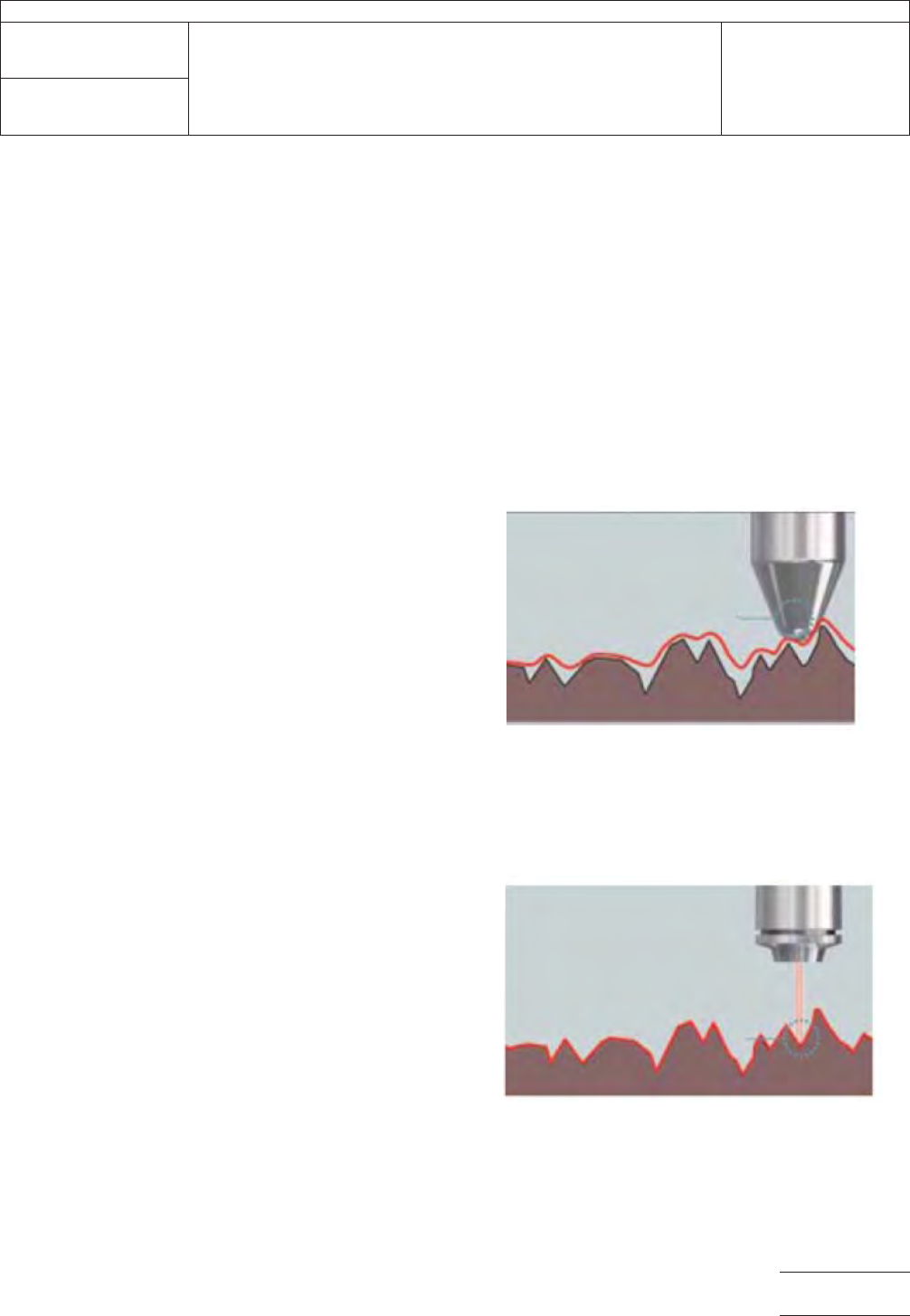
S-Filter:
• Commonly known as a low-pass filter.
• This filter is equivalent to λs for line roughness defined by
ISO 4287.
• Eliminates noisy data that varies based on the size of beam
spot. This will vary based on the objective lens chosen for
the analysis. (see below for explanation)
Low mag lens, larger beam spot, high
S-filter value
High mag lens, smaller beam spot, low
S-filter value
Vs.
IPC-TM-650
Number
2.2.22
Subject
Noncontact Metallic Foil Surface Topography/Texture
Date
5/20
Revision
Page3of5