IPC-TM-650 EN 2022 试验方法.pdf - 第428页
5.3.2 Dissipation Factor The dissipation factor value is read directly from the digital display. 5.4 Report The report shall contain the following: 1. Measurement of effective thickness of specimens tested. 2. Capacitanc…

1.0
Scope
This
test method is to determine the dielectric
constant and dissipation factor of raw printed wiring board
material at 1 MHz.
2.0
Applicable Documents
None
3.0
Test Specimens
Each
specimen shall be 50.8 ± 0.076
mm [2.0 ± 0.003 in] in diameter by thickness of laminate or
substrate material. Remove copper of metal-clad specimens
by etching using standard commercial practices. At least
three specimens are required.
4.0
Equipment/Apparatus
4.1 Meter
A
1 MHz Digital LCR Meter, Hewlett Packard
Mdl 4271A or equivalent.
4.2
Test Fixture
Hewlett
Packard Mdl 16022A test fixture
or equivalent.
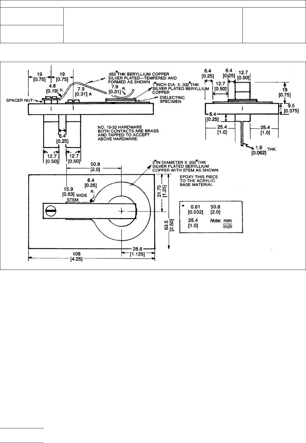
4.3
Specimen Holder
A
special specimen holder made as
shown in Figure 1. This holder is designed to be compatible
with the H/P test fixture, Mdl 16022A.
4.0
Procedure
5.1 Preparation
5.1.1
Prepare
the specimens as specified in paragraph 3.0.
5.1.2 Calculate
the effect thickness (inches) =
0.01942 x Mass
Density
Mass
= Measured weight in grams
Density = Grams per cubic cm (as per ASTM-D-792,
Method 1A)
5.1.3
Coat
both sides of specimens with one uniform coat-
ing of silver conductive paint.
5.1.4
Air-dry
the specimens until dry to touch, then oven-dry
at 50°±2°C for 1/2 hour and cool in a desiccator.
5.1.5
Punch
or machine a 25.4 mm [1.0 in] diameter disc
from the 50.8 mm [2.0 in] specimens. (Assure that there is no
carry over of the paint from one side to the other.)
5.1.6 Condition
the 25.4 mm [1.0 in] specimens for a mini-
mum of 40 hours at 23°±5°C at a relative humidity of 50%.
5.2
Testing
5.2.1
Turn
meter on and allow to warm up for 60 minutes
minimum.
5.2.1.1
Set
the controls on the meter as follows:
Function – C-D
Range – Manual
Trigger – Internal
Rate – FCW
Test Signal Level – Low
5.2.1.2
Connect
the cables for the test fixture to the appro-
priate connectors.
5.2.2
Plug
the special specimen holder into the test fixture.
5.2.3
The
digital display on the meter will show the capaci-
tance value and the dissipation factor of the unknown dielec-
tric specimen.
5.3
Calculation
5.3.1 Dielectric Constant
The
dielectric constant shall be
determined by using the following formula:
K =
Ct
0.225
A
K = Dielectric constant
C = Capacitance reading from Mdl 4271A Meter
A = Area of a 1-inch disc (square inches)
t = Effective thickness (inches)
The
Institute for Interconnecting and Packaging Electronic Circuits
2215 Sanders Road • Northbrook, IL 60062
IPC-TM-650
TEST
METHODS MANUAL
Number
2.5.5.2
Subject
Dielectric
Constant and Dissipation Factor of
Printed Wiring Board Material—Clip Method
Date
12/87
Revision
A
Originating Task Group
N/A
Material
in this Test Methods Manual was voluntarily established by Technical Committees of the IPC. This material is advisory only
and its use or adaptation is entirely voluntary. IPC disclaims all liability of any kind as to the use, application, or adaptation of this
material. Users are also wholly responsible for protecting themselves against all claims or liabilities for patent infringement.
Equipment referenced is for the convenience of the user and does not imply endorsement by the IPC.
P
age1of2
电子技术应用 www.ChinaAET.com
5.3.2
Dissipation Factor
The
dissipation factor value is
read directly from the digital display.
5.4
Report
The
report shall contain the following:
1. Measurement of effective thickness of specimens tested.
2. Capacitance values of the specimens tested.
3. Calculated dielectric constants and averaged measure-
ment.
4. Dissipation factor values and averaged measurement.
6.0 Notes
6.1
The
dielectric constant is defined as the ratio of the
capacitance with the test material between the two plates to
the capacitance of air between two plates.
6.2
The
dissipation factor of a dielectric material is the rela-
tionship between the permittivity (capacitance of material) and
conductivity (ability to conduct or the reciprocal of the electri-
cal resistivity) measured at a given frequency.
IPC-2552-1
Figure
1 Special Test Fixture for Dielectric Constant and Dissipation Factor Measurements
IPC-TM-650
Number
2.5.5.2
Subject
Dielectric
Constant and Dissipation Factor of Printed Wiring
Board Material—Clip Method
Date
12/87
Revision
A
P
age2of2
电子技术应用 www.ChinaAET.com

1.0
Scope
1.1 Purpose
This
method is suitable for determining the
volume permittivity, (dielectric constant) and loss tangent (dis-
sipation factor) of insulating materials at 1 MHz. It is not
dependent on either direct or indirect measurement of speci-
men thickness and therefore is very useful for thin films and
laminates but may also be used on specimens up to approxi-
mately 6.35 mm [0.25 in] thick.
It is useful for all ranges of permittivity and for loss tangent as
low as 0.0005 providing the range and accuracy of the bridge
used are adequate.
1.2
Description of Method
The
two fluid method utilizes
air as one fluid and a suitable liquid, normally Dow 200 1.0CS
silicone fluid, as the second. Using an established value for
the permittivity of air, the values for the permittivity of the fluid
and the sample may easily be calculated. The cell spacing is
fixed during all readings but does not need to be known accu-
rately for the series of readings required. Since specimens do
not require any electrodes to be applied and since many
specimens can be measured at one time without changing
any spacings or machine settings, the method is not only very
accurate but very rapid.
The method has been used for measurement of PTFE and
epoxy glass laminates and flexible films, e.g., polyimide.
Reproducibility lab to lab is excellent for permittivity provided
minimal precautions are observed and bridge accuracy is
appropriate. On most materials, the effects of small changes
in moisture or temperature are larger than any error due to the
method. Lab to lab correlation on stable material such as
PTFE have shown results to be consistently within 0.005 or
(0.20%).
2.0
Applicable Document
3.0 Test Specimens
3.1 Number
Unless
otherwise specified in the material
specification, one specimen is adequate for materials which
are uniform, e.g., unreinforced plastics. For woven reinforced
materials where resin content may vary, at least 2 specimens,
representing the thinnest and thickest part of the sample,
should be tested. For material with random reinforcement, a
minimum of three specimens from the edge and center of the
sheet are recommended to characterize variation within the
sheet.
3.2
Form
Individual
specimens shall be 81.3 mm ± 1.3 mm
x 81.3 to 101.6 mm [3.2 in ± 0.05 in x 3.2 in to 4.0 in] x thick-
ness.
For materials under 0.254 mm [0.010 in], individual specimens
should be stacked to a minimum of 0.381 mm [0.015 in] to
maximize accuracy. Thinner specimen buildups may be used
if the correlation with the 0.381 mm [0.015 in] specimen is
within the required accuracy for the particular equipment, cell
spacing and material being tested.
3.3
Foil Clad Materials
All
foil clad materials shall have the
metal cladding completely removed by etching and shall be
rinsed and dried prior to conditioning.
3.4
Marking
Mark
each specimen in the upper left corner
with an engraving pencil or an ink which is not soluble in the
Dow Corning 200 fluid.
4.0
Apparatus/Materials
4.1
1
MHz Capacitance Bridge with 0-200 (or 0-100) pf
range.
1
4.2
Cell
Balsbaugh
LD-3
2
or
equivalent (see Figure 1) three
terminal cell. Note: For accuracy of 1% or better, room tem-
perature must not vary more than 1°C during measurements.
Temperature control is necessary if laboratory variation
exceeds these limits.
1.
Capacitance Bridge—Suggested is Boonton 76A automatic capacitance bridge. This model has adequate capacitance range and adequate conductance resolu-
tion (0.001 microsiemen) to permit measurement of dissipation factors down to approximately 0.0005. Other bridges, e.g., Boonton 75D, are also adequate for
low loss materials and some other bridges may be suitable for higher loss materials, such as epoxy where dissipation factors exceed 0.01 and resolution of 0.01
microsiemen or even 0.1 microsiemen may be adequate.
2. Balsbaugh LD-3 Gillian and Co,, Watertown, MA, (617) 624-5688 or Zincast Corporation, 44 Homestead Ave., Stanford, CT 06902, (203) 359-0109
The
Institute for Interconnecting and Packaging Electronic Circuits
2215 Sanders Road • Northbrook, IL 60062
IPC-TM-650
TEST
METHODS MANUAL
Number
2.5.5.3
Subject
Permittivity
(Dielectric Constant) and Loss Tangent
(Dissipation Factor) of Materials (Two Fluid Cell
Method)
Date
12/87
Revision
C
Originating Task Group
N/A
Material
in this Test Methods Manual was voluntarily established by Technical Committees of the IPC. This material is advisory only
and its use or adaptation is entirely voluntary. IPC disclaims all liability of any kind as to the use, application, or adaptation of this
material. Users are also wholly responsible for protecting themselves against all claims or liabilities for patent infringement.
Equipment referenced is for the convenience of the user and does not imply endorsement by the IPC.
P
age1of4
电子技术应用 www.ChinaAET.com