IPC-TM-650 EN 2022 试验方法.pdf - 第638页
IPC-2.5.33.3-1 Figure 1 Apparatus for Current Leakage Measurement MILLI- VOL T METER ELECTRODE (–) GROUND REFERENCE POINT 1.00 KOHM RESIST OR LEAKAGE CURRENT UNIT UNDER TEST (UUT) LOW FORW ARD-BIAS DIODES (HEADS-TO-T AIL…

4.5.4
Resistor,
1.00 KΩ, 1% (any commercially available
brand carbon or metal film)
4.5.5
Diodes (two) shall be of the lowest practicable known
forward bias devices. 1N34 diodes have been found satisfac-
tory for this purpose.
4.5.6
AC
Receptacles (two)
4.5.7
Line
cord
4.5.8
Strain
relief
4.5.9
BNC
connector
4.5.10
Edge
Card Connector w/mounting hardware
4.5.11
Metal
(bud) box
4.6
Preparation of Apparatus
Connect
the apparatus as
illustrated in Figure 1. The diodes shall be wired head-to-tail to
be effective regardless of the applied signal’s polarity (± DC or
AC). The negative electrode of the apparatus must make
good electrical contact with the ground reference point. These
connections will be automatic when using the test box
detailed in Figure 2. Configure the UUT for typical operation.
In those UUT’s that utilize additional functions (such as pres-
sure or vacuum), provide switching actuation for these func-
tions.
Note:
The
plugs are in power receptacles during measure-
ments. They are shown unplugged here for clarity. Non-US
power receptacles may be different from those illustrated.
4.7
Calibration & Standardization
The
millivoltmeter shall
bear a current calibration sticker. If an oscilloscope is used,
the probe shall be adjusted to display the square wave cali-
bration signal generated by the oscilloscope without under-
shoot or overshoot.
5
Procedure
5.1 DC Measurement
Configure
the millivoltmeter for
measuring DC. Turn on the UUT and allow it to warm up to a
normal operating temperature. Touch the hot tip of the UUT to
the tinned area of the test electrode. Apply solder to form
good electrical contact. Let the tip dwell on the electrode
while the UUT cycles power to maintain temperature. Operate
various other functions of the UUT if present, such as the
vacuum pump or air solenoid by actuating the UUT’s finger
switch or foot switch. Wait for the reading to stabilize, then
record the reading.
5.2
AC Measurement
The
procedure for measuring AC is
the same as for DC except the millivoltmeter is configured for
AC.
5.3
Calculation and Interpretation of Results
Even
though
the meter reads out in millivolts, using 1.00 KΩ for the
resistor value results in the displayed numbers representing
the current in microamps without calculation (i.e., a readout of
0.8 mv indicates 0.8 µA).
The DC reading shall not exceed 1.0 µA. The AC reading shall
not exceed 1.0 µA.
6 Notes
If
tracking test results, record the measured values
on a copy of the form found in Method 2.5.33.
Testing has shown that for UUTs that utilize high frequency
circuits, layout and cord positioning can influence the AC cur-
rent leakage reading. A compact configuration such as the
one shown in Figure 2 minimizes those influences.
IPC-TM-650
Number
2.5.33.3
Subject
Measurement
of Electrical Overstress from Soldering Hand
Tools - Current Leakage Measurements
Date
11/98
Revision
P
age2of3
电子技术应用 www.ChinaAET.com
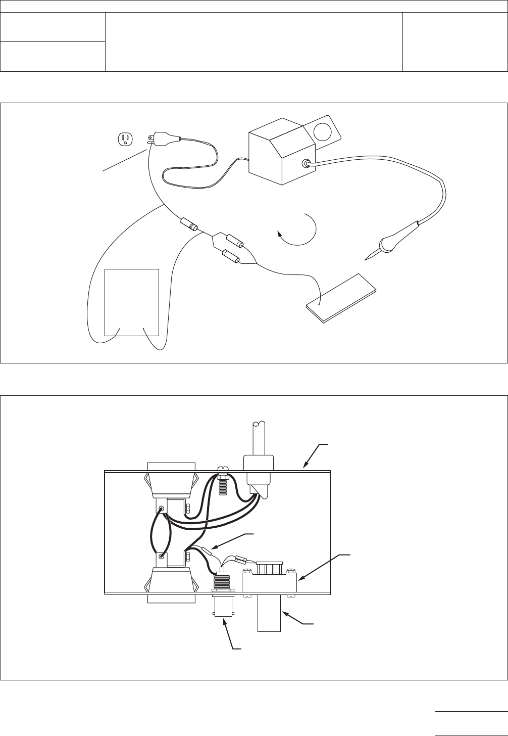
IPC-2.5.33.3-1
Figure
1 Apparatus for Current Leakage Measurement
MILLI-
VOLT
METER
ELECTRODE
(–)
GROUND
REFERENCE
POINT
1.00 KOHM
RESIST
OR
LEAKAGE
CURRENT
UNIT UNDER
TEST (UUT)
LOW FORWARD-BIAS
DIODES (HEADS-TO-TAILS)
TEST
ELECTRODES
IPC-2.5.33-1
Figure
2 Current Leakage Test Circuit Configuration (Cover Removed)
AC RECEPT
ACLE
FOR VOLTMETER
AC RECEPTACLE
FOR UUT
BNC CONNECTOR
FOR VOLTMETER
TEST ELECTRODE
CARD EDGE
CONNECTOR
1K RESISTOR
METAL BOX
DIODES
GRN
BLK
WHT
TO
AC
IPC-TM-650
Number
2.5.33.3
Subject
Measurement
of Electrical Overstress from Soldering Hand
Tools - Current Leakage Measurements
Date
11/98
Revision
P
age3of3
电子技术应用 www.ChinaAET.com
1
Scope
The
following information is a supporting docu-
ment in support of Method 2.5.33. The test methods within
this group of procedures can be falsely influenced by radio
frequency interference and electromagnetic interference from
lighting and equipment found in the workplace and testing
area. To avoid these influences, the leakage and transient
tests should be performed in a screen room. In lieu of a
screen room, this test method has been provided to make a
low cost shielded enclosure, which should provide adequate
shielding for the performance of these test procedures.
2
Applicable Documents.
ANSI/J-STD-001
Requirements
for Soldered Electrical and
Electronic Assemblies.
3
Test Specimens
None
required
4
Equipment/Apparatus
Only
general guidelines are pro-
vided. The enclosure can be made from readily available
materials obtainable from any hardware store or lumber yard.
Dimensions may be adjusted up or down to accommodate
equipment to be tested. Experience has shown that best
results will be obtained with a full length piano hinge across
the back of the lid. The lid should be secured in the closed
position with a metal, cam-type locking mechanism. The
screening material from the lid should contact the material
covering the sides to ensure a complete seal.
In addition to information on the enclosure, Section 6 also
includes information on the filtered AC power module and test
electrode mounting that should be incorporated into the local
design to achieve best performance.
5
Procedure
No
construction procedure is provided. Each
local activity should construct the enclosure to meet their spe-
cific needs based on the information in Section 6.
6 Notes
6.1
Shielded Enclosure
High
measuring impedance is
used so as not to load down the signal being generated by
the UUT. Because a high measuring impedance is used,
there’s a threat that transients emanating from sources other
than the UUT might be displayed. To prevent the apparatus
from picking up ambient EMI/RFI, the UUT is placed inside a
‘‘benchtop’’ shielded enclosure. Filtered AC line voltage is
available from within.
Some construction suggestions are given in 6.2 and 6.3.
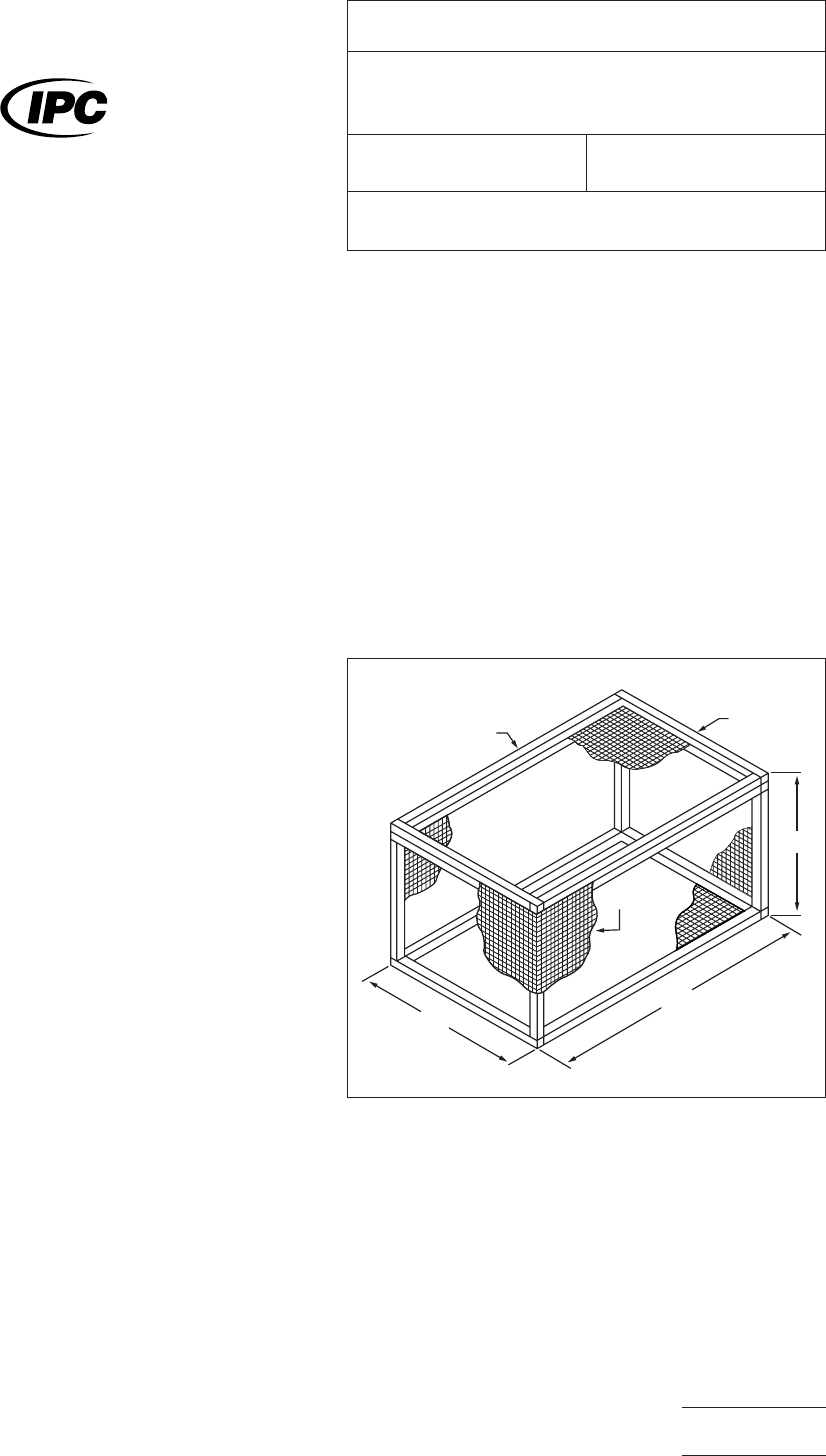
6.2
Basic Enclosure
Although
Figure 1 illustrates wire
mesh walls, sheet metal walls also work. Metals other than
copper or brass may be used. If mesh is used, it should be
6.5 mm or tighter weave. Whatever metallic materials are
used, continuity across seams and to the lid should be
ensured.
Figure 2 suggests a way for mounting to an AC power entry.
6.3
Test Electrode
The
test electrode (see Figure 3) is
shown mounted to the sidewall of the enclosure to facilitate
connection of test equipment to the UUT. Moving this struc-
ture entirely into shielded enclosure and providing an access
port through which test cables may be routed will slightly
increase the construction cost, but will also serve to better
isolate the test setup.
IPC-2.5.33.4-1
Figure
1 Enclosure Construction Suggestion
51 cm
81 cm
43 cm
LID
WOOD
SHEET
METAL
OR WIRE MESH
The
Institute for Interconnecting and Packaging Electronic Circuits
2215 Sanders Road • Northbrook, IL 60062
IPC-TM-650
TEST
METHODS MANUAL
Number
2.5.33.4
Subject
Measurement
of Electrical Overstress from
Soldering Hand Tools - Shielded Enclosure
Date
11/98
Revision
Originating Task Group
Manual Soldering Task Group (5-22c)
Material
in this Test Methods Manual was voluntarily established by Technical Committees of the IPC. This material is advisory only
and its use or adaptation is entirely voluntary. IPC disclaims all liability of any kind as to the use, application, or adaptation of this
material. Users are also wholly responsible for protecting themselves against all claims or liabilities for patent infringement.
Equipment referenced is for the convenience of the user and does not imply endorsement by the IPC.
P
age1of3
电子技术应用 www.ChinaAET.com