IPC-TM-650 EN 2022 试验方法.pdf - 第597页
49°C and 60°C. Coat unclad side with silver conductive paint (per Figure 2). Sand all edges to remove any silver paint to prevent a conductive path. 5.1.3 Bare Dielectric Prepare test specimens by immers- ing in distille…
1
Scope
This
test method is designed to determine both
the volume (cross-sectional) and surface electrical resistance
of the dielectric material under humid conditions.
2 Applicable Documents
ASTM-D-257
DC
Resistance or Conductance of Insulating
Materials
3
Test Specimens
At
least two specimens 10 cm x 10 cm
x thickness.
4
Apparatus
4.1 Chamber
A
test chamber capable of maintaining a
combination of 35°C ± 2°C and 90% -0, +5% relative humid-
ity (RH).
4.2
Drying Chamber
A
chamber capable of maintaining
80°C.
4.3
Meter
A
Keithly model L-7 megohmmeter, or equiva-
lent.
4.4
Miscellaneous
Desiccator,
silver paint, conductor
composition 4817 by DuPont Co. or equivalent, distilled water
source, calcium chloride desiccant, analytical balance. Fabri-
cation of a special test fixture (such as a Balsbaugh Fixture)
may be desirable if frequent testing is required.
5
Procedure
5.1 Sample Preparation for Volume Resistivity
5.1.1 Double Clad Laminate
Prepare
etched conductor
test specimens in accordance with Figure 1 for one side and
Figure 2 for other side using standard commercial practices.
Immerse each specimen in distilled water for 24 hours at 23°C
± 2°C, then dry in oven for two hours at a temperature
between 49°C and 60°C.
5.1.2
Single Clad Laminate
Prepare
test specimens by
etching the foil, single clad laminate per Figure 1, then clean (if
etched) by immersion in distilled water for 24 hours at 23°C ±
2°C, then dry in oven for two hours at a temperature between
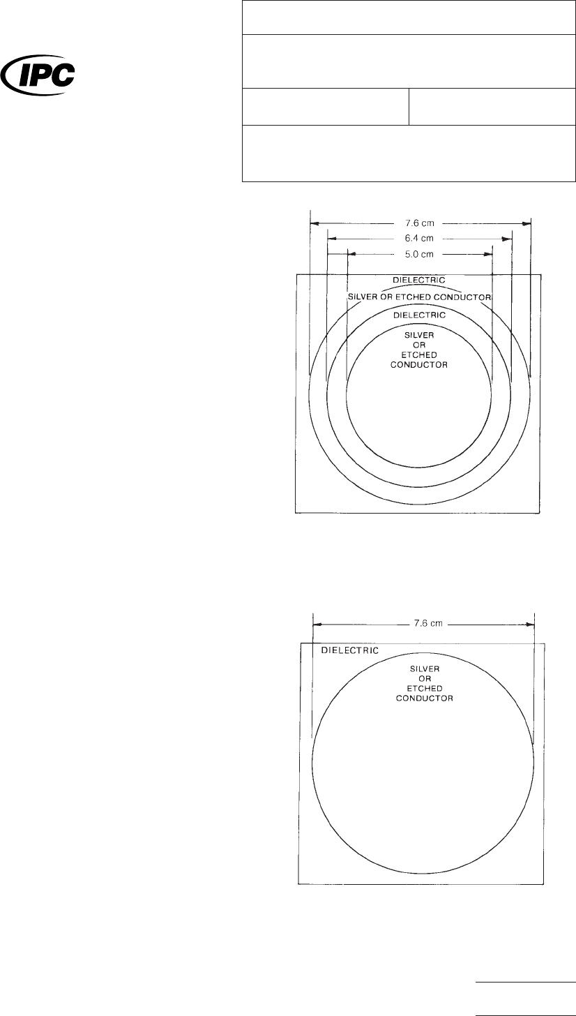
IPC-2517-1
Figure
1 Volume and Surface Resistivity Test Pattern.
(Side 1)
IPC-2517-2
Figure
2 Volume and Surface Resistivity Test Pattern.
(Side 2)
The
Institute for Interconnecting and Packaging Electronic Circuits
2215 Sanders Road • Northbrook, IL 60062
IPC-TM-650
TEST
METHODS MANUAL
Number
2.5.17
Subject
Volume
Resistivity and Surface Resistance of
Printed Wiring Materials
Date
5/98
Revision
E
Originating Task Group
Flex Peel Strength Test Methods Task Group
(D-13A)
Material
in this Test Methods Manual was voluntarily established by Technical Committees of the IPC. This material is advisory only
and its use or adaptation is entirely voluntary. IPC disclaims all liability of any kind as to the use, application, or adaptation of this
material. Users are also wholly responsible for protecting themselves against all claims or liabilities for patent infringement.
Equipment referenced is for the convenience of the user and does not imply endorsement by the IPC.
P
age1of2
电子技术应用 www.ChinaAET.com

49°C
and 60°C. Coat unclad side with silver conductive paint
(per Figure 2). Sand all edges to remove any silver paint to
prevent a conductive path.
5.1.3
Bare Dielectric
Prepare
test specimens by immers-
ing in distilled water for 24 hours at 23°C ± 2°C, then dry in
an oven for two hours at a temperature between 49°C and
60°C. Coat the unclad material with silver conductive paint
(one side per Figure 1 and the other per Figure 2). Sand all
edges to remove any silver paint.
5.2
Conditioning
5.2.1
Condition
specimens together with the test fixture at
35°C ± 2°C and 90% -0, +5% RH for 96 hours.
5.2.2
Specimens
(and test fixture) must remain in the cham-
ber for all phases of both the volume resistivity and surface
resistance tests.
5.2.3
These
conditions may vary depending on the request
of the material user.
5.3
Test
5.3.1
After
conditioning, and without removing specimens
from the chamber, connect specimen to electrodes as fol-
lows:
Megohmmeter
Leads Specimen Location
High
.................................................. Guarded (5.0 cm circle)
Ground ...............................................Guarded (6.35 cm ring)
Test ................................................Unguarded (7.6 cm circle)
5.3.2
Turn
on the megohm meter and allow to warm up for
a minimum of 15 minutes.
5.3.3
After
warm up, calibrate meter and adjust internal volt-
age to 500 volts DC.
5.3.4
Read
the meter (in megohms) after the test switch is
held depressed for 60 seconds.
5.4
Evaluation
5.4.1
Calculate
the volume resistivity (r) in megohm centime-
ters as derived from the following formula:
r =
RA
L
r
= volume resistivity in megohm cm
L = thickness of specimen in cm
A = area of guarded electrodes is 25.6 cm
2
R
= volume resistance in megohms (meter reading)
5.5
Preparation for Surface Resistance
Leave
the same
specimens in the test chamber and prepare to test surface
resistance by connecting the specimens to electrodes as fol-
lows:
Megohmmeter
Leads Specimen Location
High
...........................................................................Guarded
Ground ..................................................................Unguarded
Test ...............................................................................Guard
5.6
Test
Perform
the same testing procedures per 5.3.
5.7
Evaluation
The
surface resistance is the direct reading
of the megohmmeter scale and should be recorded in mego-
hms.
6 Notes
This
method may also be used for rigid dielectric
materials.
6.1
For
additional information see ASTM-D-257, DC Resis-
tance or Conductance of Insulating Materials.
IPC-TM-650
Number
2.5.17
Subject
Volume
Resistivity and Surface Resistance of Printed Wiring
Materials
Date
5/98
Revision
E
P
age2of2
电子技术应用 www.ChinaAET.com

1.0
Scope
This
test method is designed to determine vol-
ume resistivity and surface resistivity of metallic-clad or unclad
laminates under conditions of specified humidity and tempera-
ture and at elevated temperatures.
2.0
Applicable Documents
ASTM-D-257 D-C Resistance or Conductance of Insulating
Materials
IPC-TM-650
Method
2.3.6, Etching, Ammonium Persulfate
Method, 2.3.7 Etching, Ferric Chloride
Method 2.3.7.1, Cupric Chloride Etching
Method 2.6.3, Moisture and Insulation Resistance, Rigid,
Rigid/Flex and Flex Printed Wiring Boards
3.0
Test Specimens
3.1
Laminate
thickness of 0.51 mm [0.020 in] or greater.
Three specimens of dimensions 101.6 ± 3.2 mm x 101.6 ±
3.2 mm [4.0 ± 0.125 in x 4.0 ± 0.125 in] by thickness shall be
prepared for each test condition, unless otherwise specified.
3.2
Laminate
thickness of less than 0.51 mm [0.020 in].
Three specimens of dimensions 50.8 ± 1.6 mm x 50.8 ± 1.6
mm [2.0 ± 0.062 x 2.0 ± 0.062 in] by the thickness shall be
prepared for each test condition, unless otherwise specified.
4.0
Equipment Apparatus
4.1
Conditioning
chamber capable of maintaining 35 ± 2°C
[95 ± 3.6°F] and 90 +5, –0% relative humidity.
4.2
Conditioning
chamber capable of attaining the tempera-
ture and humidity conditions specified in IPC-TM-650, Method
2.6.3.
4.3
Air
circulating oven capable of maintaining the specified
test temperatures to within ± 2°C[±3.6°F].
4.4
Resistance
measuring instrumentation capable of mea-
suring to 10
12
meg-ohms,
minimum, with an accuracy of ± 5
percent at its highest scale setting. The equipment shall have
the capability of applying 500 volts dc to the test specimen.
4.5
A
system/fixture for electrical connections into the tem-
perature and humidity chambers (see 4.1, 4.2, 4.3). Three
separate cables shall be provided to make connections to
each specimen being conditioned/tested. The center conduc-
tor of each cable shall be connected to one of the three elec-
trodes applied to the test specimen. The opposite ends of the
cables shall be brought outside the chamber and terminated
at a convenient location for connection to the measuring
instrument. Shields shall be trimmed back from the ends of
the center conductor insulation and interconnected to the
guard post of the measuring instrument. See 6.2 for additional
information.
Support the specimen parallel to the air flow through the
chamber during conditioning.
Special care should be taken to ensure that materials used in
the fixture are such that resistance readings are that of the
material being tested and not the fixture.
4.6
A
measurement device capable of measuring laminate
thickness to the nearest 0.0025 mm [0.0001 in].
4.7
Material
and apparatus for formation of specimen con-
ductors.
4.7.1 Conductor
silver paint; composition 4817 by Dupont
Company, or equivalent.
4.7.2
A
system for applying the paint to the specimen, such
as silk screening.
4.7.3
A
mask, fixture, photoprinting system, or equivalent,
for applying the applicable electrodes/test pattern to the
specimen (See Dimension Table).
4.8
Etching
system in accordance with IPC-TM-650,
Method 2.3.6, 2.3.7, or 2.3.7.1.
5.0 Procedure
5.1 Specimen Preparation
5.1.1
Test
patterns with the applicable dimensions shown in
the Dimension Table, and in accordance with Figures 1, 2,
and 3 shall be generated, as follows:
The
Institute for Interconnecting and Packaging Electronic Circuits
2215 Sanders Road • Northbrook, IL 60062
IPC-TM-650
TEST
METHODS MANUAL
Number
2.5.17.1
Subject
Volume
and Surface Resistivity of Dielectric
Materials
Date
12/94
Revision
A
Originating Task Group
MIL-P-13949 Test Methods Task Group (7-11b)
Material
in this Test Methods Manual was voluntarily established by Technical Committees of the IPC. This material is advisory only
and its use or adaptation is entirely voluntary. IPC disclaims all liability of any kind as to the use, application, or adaptation of this
material. Users are also wholly responsible for protecting themselves against all claims or liabilities for patent infringement.
Equipment referenced is for the convenience of the user and does not imply endorsement by the IPC.
P
age1of4
电子技术应用 www.ChinaAET.com