IPC-TM-650 EN 2022 试验方法.pdf - 第628页
6.5 Reference MIL-STD-1686 1 Electrostatic Discharge Control Program for Protection of Electrical and Electronic Parts, Assemblies and Equipment (Excluding Electrically Initiated Explosive Devices) MIL-HDBK-263 Electrost…
6.4
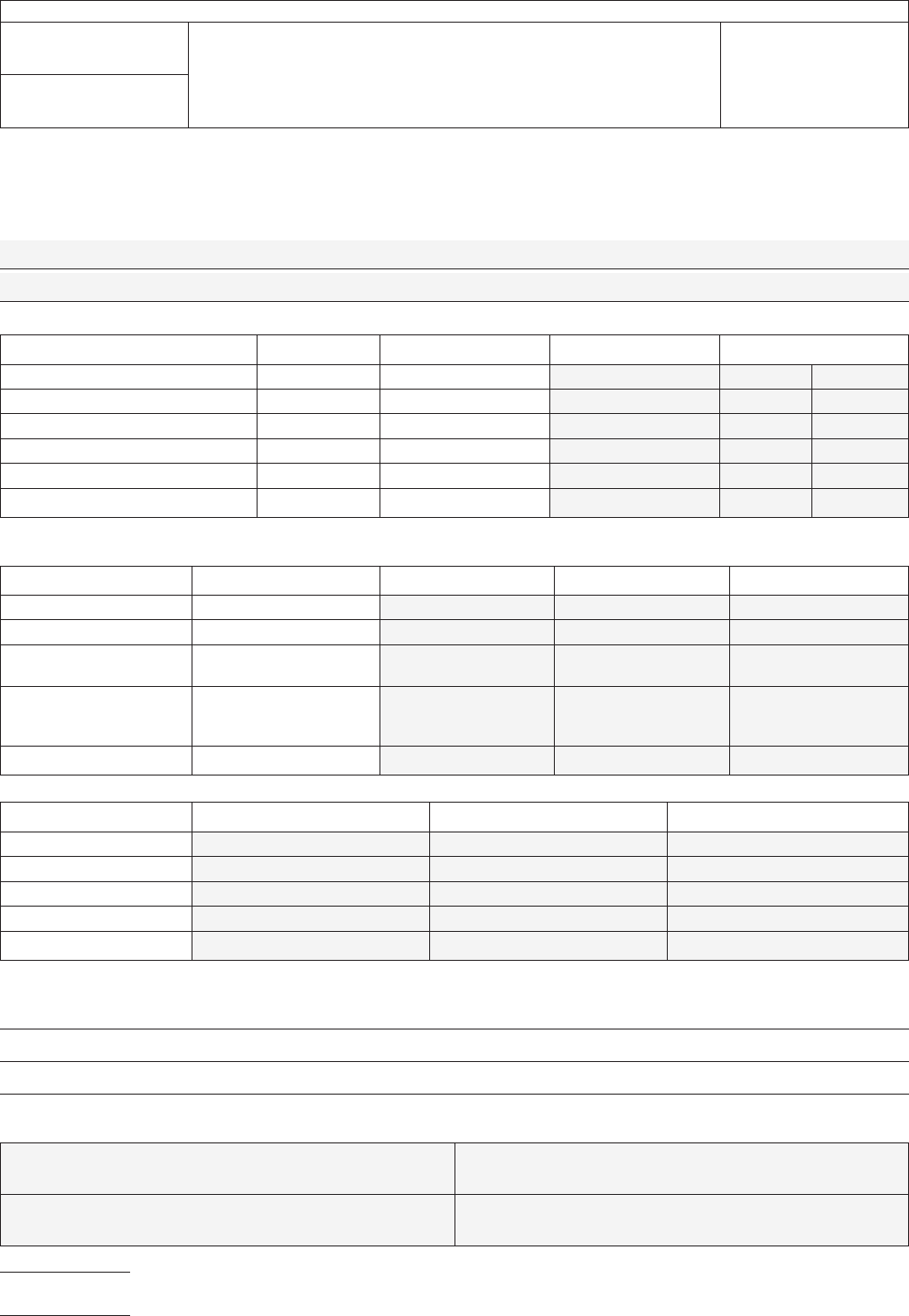
Test Results
Complete
ALL shaded areas.
Description
of UUT (brand, model configuration, etc.):
T
est Procedure Pass/Fail Criteria Value Recorded Status
Ground
Measurements (2.5.33.1) ≤5 ΩΩ[ Pass [ Fail
Transient Measurements/Pass 1 (2.5.33.2) ≤2 V peak V [ Pass [ Fail
Transient Measurements/Pass 2 (2.5.33.2) ≤2 V peak V [ Pass [ Fail
Transient Measurements/Pass 3 (2.5.33.2) ≤ 2 V peak V [ Pass [ Fail
Current Leakage Measurements (2.5.33.3) ≤1.0 µ-amp DC µ-amp DC [ Pass [ Fail
Current Leakage Measurements (2.5.33.3) ≤1.0 µ-amp ACrms µ-amp ACrms [ Pass [ Fail
Description of Test Equipment and Configuration
Equipment
Function Brand Model Calibration Date
AC
millivoltmeter true mvAC/rms
DC millivoltmeter 60 mv DC
Ohmmeter resistances beyond 5
MΩ
Storage Oscilloscope 100 Mhz bandwidth or
faster, 1 MΩ input
vertical amplifier
Constant Current Source 10 milliamps DC
Equipment
Scale Used Cal / Std Meas. Baseline Meas.
AC
millivoltmeter
DC millivoltmeter
Ohmmeter
Storage Oscilloscope
Constant Current Source
Additional Comments:
Test
Completed by:
NAME:
DATE:
COMPANY: PHONE:
IPC-TM-650
Number
2.5.33
Subject
Measurement
of Electrical Overstress from Soldering Hand
Tools
Date
11/98
Revision
P
age4of5
电子技术应用 www.ChinaAET.com

6.5
Reference
MIL-STD-1686
1
Electrostatic
Discharge Control Program for
Protection of Electrical and Electronic Parts, Assemblies and
Equipment (Excluding Electrically Initiated Explosive Devices)
MIL-HDBK-263
Electrostatic
Discharge Control Handbook
for Protection of Electrical and Electronic Parts, Assemblies
and Equipment (Excluding Electrically Initiated Explosive
Devices)
EOS/ESD-S6.0-1994
2
Grounding
- Recommended Practice
1.
Standardization Documents Order Desk, 700 Robbins Avenue, Bldg. 4D, Philadelphia, PA 19111-5094
2. ESD Association, 7902 Turin Rd., Ste. 4, Rome, NY 13440-2069
IPC-TM-650
Number
2.5.33
Subject
Measurement
of Electrical Overstress from Soldering Hand
Tools
Date
11/98
Revision
P
age5of5
电子技术应用 www.ChinaAET.com

1
Scope
This
test method describes the measurement of
the DC tip-to-ground resistance of an electric hand soldering/
desoldering tool designed with a grounded tip. Measurement
of tip-to-ground AC reactance is outside the scope of this test
method. Also, measurement of soft grounded or equipment
with insulated tips is outside the scope of this test method.
There are three times when ground testing should be done:
• Equipment qualification for purchase
• Incoming inspection of new or repaired equipment
• Process monitoring (periodic checks)
Determination of tip-to-ground resistance is accomplished by
using a basic ohmmeter circuit, passing a current through the
tip and its grounding circuit and measuring the resultant volt-
age drop. The values used in this test eliminate error caused
by the Seebeck (thermocouple) effect.
Warning
This
is a laboratory test procedure that may, of
necessity, expose terminals that carry line voltages. All stan-
dard laboratory safety procedures regarding the setup and
performance of tests with line voltage equipment must be
observed at all times.
Caution
This
test is performed with soldering systems at
their normal operating temperature. Test personnel must take
adequate precautionary steps to protect themselves and oth-
ers from potential burns.
2
Applicable Documents.
ANSI/J-STD-001
Requirements
for Soldered Electrical and
Electronic Assemblies.
IPC-TM-650
Test
Methods Manual
2.5.33 Measurement of Electrical Overstress from Solder-
ing Hand Tools
3
Test Specimens
Test
specimens for this procedure are
detailed in Method 2.5.33.
4
Equipment/Apparatus
4.1
Test
electrode per Method 2.5.33
4.2
Constant
current source capable of providing 10 milli-
amps DC
4.3
DC
millivoltmeter capable of measuring at least 60 mv
DC and having a resolution of 1 mv DC
4.4
Resistor,
4.99Ω 1% precision
1
⁄
4
w
or greater (any com-
mercially available brand carbon or metal film)
4.5
Preparation of Apparatus
Connect
the apparatus as
illustrated in Figure 1. The negative electrode of the test appa-
ratus shall make a good electrical connection to the ground
reference point of the Unit Under Test (UUT). The UUT shall be
turned on and adjusted (if applicable) to achieve normal oper-
ating temperature.
Note: The plug is in the receptacle during measurements.
It’s shown unplugged in Figure 1 for clarity. Non-US power
receptacles may be different from that illustrated.
4.6 Calibration and Standardization
The
apparatus is
checked by separately placing two resistive elements across
the test apparatus’s electrodes: a shorting wire (0.0Ω) and
4.99Ω 1% precision
1
⁄
4
w
or greater resistor. The combination
of the current source and the measuring/indicating device will
be accurate to within ± 0.2Ω (± 4% of upper limit).
5
Procedure
Once
the electrodes are in position and the
test apparatus is operating, touch the HOT tip of the UUT to
the tinned area of the test electrode. Apply solder to form a
good electrical contact. Wait for the reading to stabilize, then
record the reading.
5.1
Calculation and Interpretation of Results
Even
though
the meter reads out millivolts, using 10 ma DC for
excitation current results in the displayed numbers represent-
ing the resistance in ohms without calculation, except for
decimal place shifting (i.e., a readout of 30 mv dc indicates
3.0Ω).
The reading shall be equal to or less than 5.0Ω.
6 Notes
If
tracking test results, record the measured values
on a copy of the form found in Method 2.5.33.
The
Institute for Interconnecting and Packaging Electronic Circuits
2215 Sanders Road • Northbrook, IL 60062
IPC-TM-650
TEST
METHODS MANUAL
Number
2.5.33.1
Subject
Measurement
of Electrical Overstress from
Soldering Hand Tools - Ground Measurements
Date
11/98
Revision
Originating Task Group
Manual Soldering Task Group (5-22c)
Material
in this Test Methods Manual was voluntarily established by Technical Committees of the IPC. This material is advisory only
and its use or adaptation is entirely voluntary. IPC disclaims all liability of any kind as to the use, application, or adaptation of this
material. Users are also wholly responsible for protecting themselves against all claims or liabilities for patent infringement.
Equipment referenced is for the convenience of the user and does not imply endorsement by the IPC.
P
age1of3
电子技术应用 www.ChinaAET.com