IPC-TM-650 EN 2022 试验方法.pdf - 第478页
IPC-2257a-5-4 Figure 5-4 Determination of instant in the TDR waveform corresponding to the beginning of the reference line. A R,0 is the amplitude of the signal reflected from the open end of rf cable. SPD TDR INSTRUMENT …
5.1.3.2
Procedure for the Reference Line
Step
1 –
Remove
the transfer standard (or air line reference)
and hold the precision rf cable in the air and locate the instant,
t
1,Ref
,
on the TDR waveform where the rf cable/open discon-
tinuity occurs (see Figure 5-4). t
1,Ref
is
the instant in the TDR
waveform when the reflection from the open circuit has
reached 50 % of its amplitude (see Figure 5-4), unless other-
wise specified by the user.
Step
2 –
Connect
the rf cable to the reference line and locate
the instant, t
2,Ref
,
on the TDR waveform where the reference
line/open discontinuity occurs (see Figure 5-5). t
2,Ref
is
the
instant in the TDR waveform when the reflection from the
open circuit has reached 50 % of its amplitude (see Figure
5-5), unless otherwise specified by the user.
Step
3 –
Compute
the round trip propagation time of the
transmission line using:
T
rt,Ref
= t
2,Ref
− t
1,Ref
Step
4 –
Determine
the initial instant, t
i,Ref
,
of measurement
zone using:
t
i,Ref
= t
1,Ref
+ x
i%
T
rt,Ref
where x
i%
is
the lower limit of the measurement zone and is 30
% unless otherwise specified by the user.
Step
5 –
Determine
final instant, t
f,TL
,
of measurement zone
using:
t
ƒ,Ref
= t
1,Ref
+χ
ƒT
T
rt,Ref
where x
f%
is
the upper limit of the measurement zone and is
70 % unless otherwise specified by the user.
5.2
Single-Ended TDR Measurement Procedures
This
section
contains three methods for measuring the character-
istic impedance of single-ended transmission lines. The fol-
lowing calibration and measurement steps should be used
when the device(s) under test are unbalanced (single-ended)
transmission lines. This process can be followed manually but,
to improve measurement repeatability and reduce measure-
ment time, an automated measurement system is recom-
mended. Additionally, the use of a fixture based or robotic
probing system greatly improves the accuracy and repeatabil-
ity over hand probe techniques and further reduces the mea-
surement time.
5.2.1
Transfer Standard Method
In
this method, the
impedance of the reference air line is transferred to a second-
ary transmission line. The computed impedance of the sec-
ondary or transfer line then becomes the basis from which the
characteristic impedance of all subsequent test transmission
lines is computed. The transfer method provides a direct com-
parison of the impedance of the transfer standard to that of
the transmission line under test. Although this does require
two additional measurements, as compared to the in-situ
method (see 5.2.2), it does reduce the risk of damage to the
reference impedance standard due to frequent use and han-
dling. The effects of drift in TDR amplitude offset are mini-
mized with this method.
5.2.1.1
Measurement Calibration Procedure
The
instru-
ment setting must be the same for Steps 1 and 2. This pro-
cedure will determine the characteristic impedance of the
transfer standard from which characteristic impedance of the
transmission line under test will be determined (see 5.2.1.2).
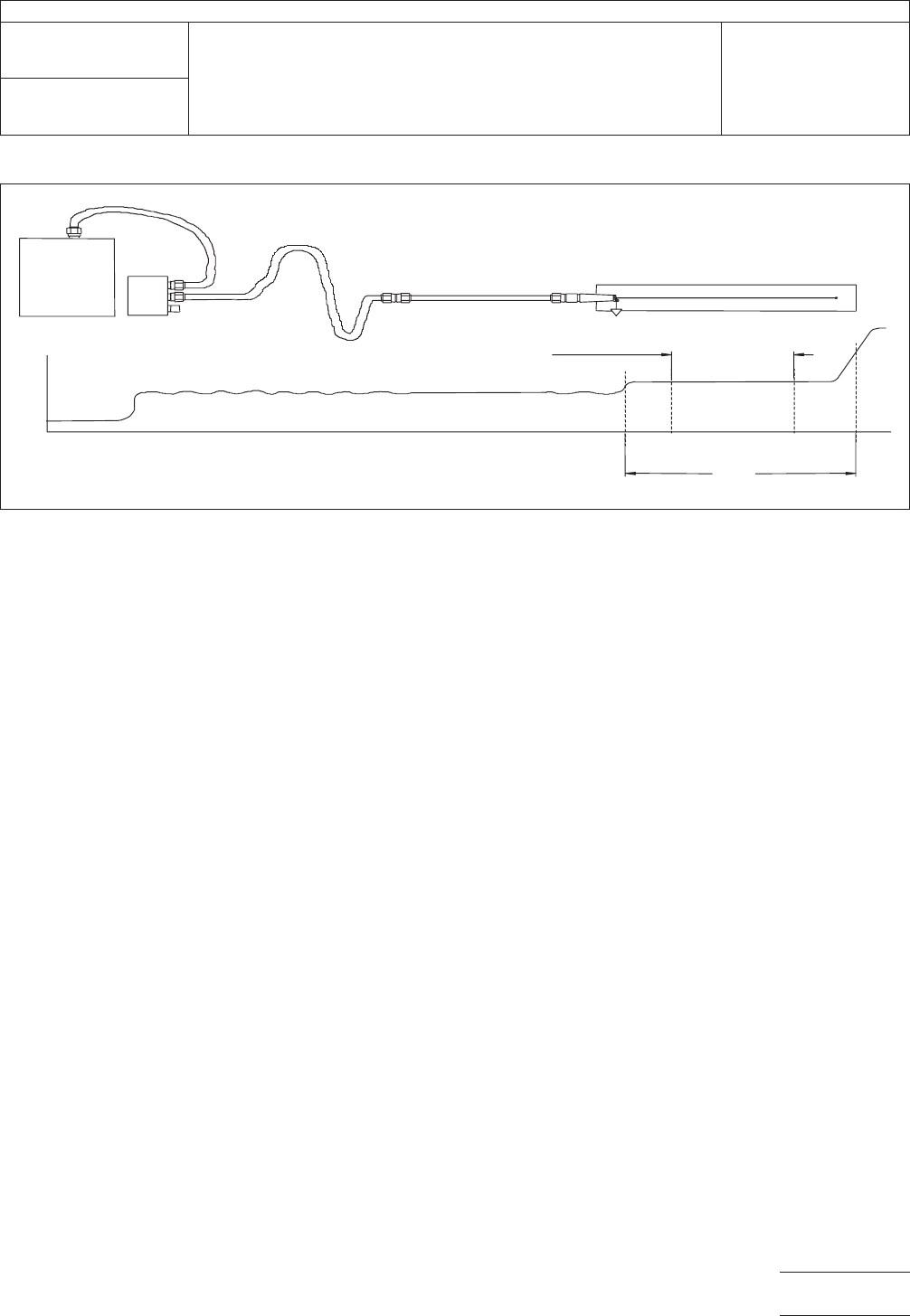
IPC-2257a-5-3
Figure
5-3 Determination of Measurement Zone
T
rt
,TL
TIME
t
1,TL
t
2,TL
SPD
TRANSFER
STANDARD
TDR
INSTRUMENT
TRANSMISSION LINE UNDER TEST
t
i,TL
t
f,TL
MEASUREMENT ZONE
for TRANSMISSION LINE UNDER TEST
PRECISION
RF CABLE
IPC-TM-650
Number
2.5.5.7
Subject
Characteristic
Impedance of Lines on Printed Boards by TDR
Date
03/04
Revision
A
P
age9of23
电子技术应用 www.ChinaAET.com
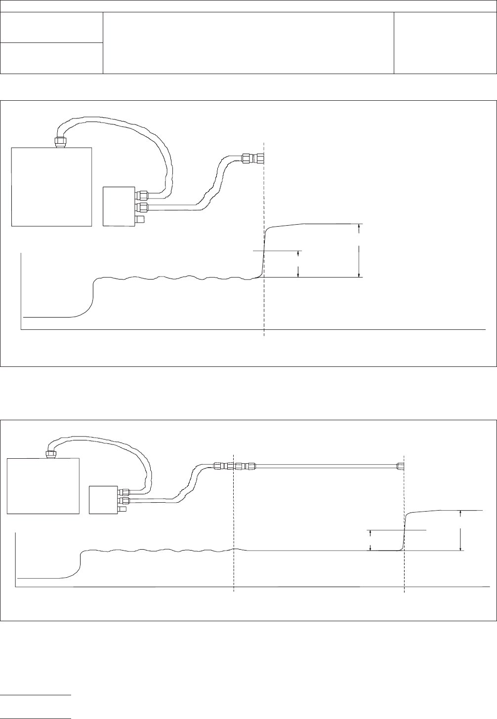
IPC-2257a-5-4
Figure
5-4 Determination of instant in the TDR waveform corresponding to the beginning of the reference line. A
R,0
is
the
amplitude of the signal reflected from the open end of rf cable.
SPD
TDR
INSTRUMENT
PRECISION
RF CABLE
t
1,Ref
TIME
0.5
A
R.0
A
R,0
IPC-2257a-5-5
Figure
5-5 Determination of instant in TDR waveform corresponding to the end of the reference line (transfer standard or
air line reference).
A
R,0
is
the amplitude of the signal reflected from the open end of the reference line.
SPD
TDR
INSTRUMENT
PRECISION
RF CABLE
t
1,Ref
TIME
0.5
A
R,0
A
R,0
REFERENCE LINE
t
2,Ref
IPC-TM-650
Number
2.5.5.7
Subject
Characteristic
Impedance of Lines on Printed Boards by TDR
Date
03/04
Revision
A
Page
10 of 23
电子技术应用 www.ChinaAET.com
Step
1 –
Hold
the probe in air (see Figure 5-6) and measure
the average voltage levels for each of those parts of the TDR
waveform corresponding to the open step, V
open
,
and to the
transfer standard, V
tran,0
. Calculate the amplitude, V
i,0
,ofthe
incident voltage step using:
V
i,0
= V
open
− V
tran,0
Step
2 –
Probe
the reference airline (see Figure 5-7) through
the appropriate interface (see 4.3.8) and measure the average
voltage levels for each of those parts of the TDR waveform
corresponding to the airline, V
std
, and
to the transfer standard,
V
tran,1
,
and compute the voltage difference, V
r,0
:
V
r,0
= V
std
− V
tran,1
The
instants, t
i,std
and t
f,std
,
shown in Figure 5-7 are anala-
gous to t
i,TL
and t
f,TL
except
that the former are for the air line
standard from which the transfer standard impedance is
determined.
Step
3 –
Calculate
the reflection coefficient of the transfer
standard relative to the air line. If the TDR system already pro-
vides reflection coefficient values, go directly to Step 4. The
reflection coefficient, ρ
tran
for
the transfer standard is given by:
ρ
tran
=
V
r,0
V
i,0
Step
4 –
Calculate
the impedance, Z
tran
, of
the transfer stan-
dard using the following formula:
Z
tran
= Z
std
1 +ρ
tran
1 −ρ
tran
5.2.1.2
Measurement Process
The
instrument setting
must be the same for Steps 1 and 2. This procedure will
determine the characteristic impedance of the transmission
line under test. This process should be done after the mea-
sure zone has been defined (see 5.1.3).
Step
1 –
Repeat
the measurements of Step 1 of 5.2.1.1. Cal-
culate the amplitude, V
i,1
,
of the incident voltage step using:
V
i,1
= V
open
− V
tran,2
where V
tran,2
is
the average voltage level of that part of the
TDR waveform corresponding to the transfer standard.
Step
2 –
Probe
the transmission line (see Figure 5-8) and
measure the mean, minimum, and maximum voltage values,
V
C,ave
,V
C,min
, and V
C,max
, of
that part of the TDR waveform
corresponding to the measurement zone of the transmission
line.
Step
3 –
Without
moving the probe from the position used in
Step 2, measure the average voltage level for that part of the
TDR waveform corresponding to the transfer standard, V
tran,3
,
and
compute the voltage difference, V
r,1
:
V
r,1
= V
tran,3
− V
C,x
where V
C,x
the
subscript ‘‘X’’ refers to ‘‘ave,’’ ‘‘min,’’ or
‘‘max.’’
Step
4 –
Calculate
the reflection coefficient of the transmis-
sion line under test relative to the transfer standard. If the TDR
system already provides reflection coefficient values, go
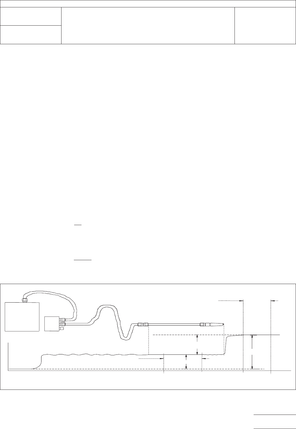
IPC-2257a-5-6
Figure
5-6 Measurement of Incident Step Amplitude
TIME
TDR
INSTRUMENT
SPD
TRANSFER
STANDARD
V
tran,0
V
open
V
i,0
MEASUREMENT ZONE
for TRANSMISSION LINE UNDER TEST
PRECISION
RF CABLE
t
i,TL
t
f,TL
MEASUREMENT ZONE
for REFERENCE LINE
t
i,Ref
t
f,Ref
IPC-TM-650
Number
2.5.5.7
Subject
Characteristic
Impedance of Lines on Printed Boards by TDR
Date
03/04
Revision
A
Page
11 of 23
电子技术应用 www.ChinaAET.com