IPC-TM-650 EN 2022 试验方法.pdf - 第403页
5.3.2 If there is a metal heat spreader on the BGA, it must be left in place until after the dye-drying step (5.11). 5.4 Section out the desired component area leaving about 19 mm to 38 mm [0.75 in to 1.5 in] of board ar…
1 Scope This test method details the dye and pull proce-
dure (formerly known as dye and pry) utilizing dye penetrant
analysis of surface-mount technology (SMT) components to
confirm assembly process parameters and solder joint quality/
integrity.
This Test Method is for observation only, to determine the
existence of dye indications.
2 Applicable Documents
IPC-7095
Design and Assembly Process Implementation for
Ball Grid Arrays (BGAs)
3 Test Specimens The specimen is a SMT part soldered
to a board. Typically, this method is used on ball grid arrays
(BGAs) to evaluate their solder joint quality/integrity; however,
it also can be used on other SMT parts, such as bottom ter-
mination components (BTCs) and connectors.
4 Apparatus or Material
4.1
Recommended dye: Red Steel Dykem® or equivalent
4.1.1 Oil-based dyes are not recommended for this
procedure.
4.2 Vacuum pump and chamber (typically a mechanical
pump and bell jar)
4.2.1 Recommend metallurgical epoxy vacuum chamber
with vacuum gauge
4.3 Stereo microscope with digital camera
4.4 Baking oven capable of 100 °C
4.5 Cutting tool to section-out desired components from the
board without exerting excessive stress on the solder joints
4.5.1 Diamond sectioning saw recommended
4.6 JB Weld or equivalent structural adhesive strong enough
to bond the tee nut to the part package surface and withstand
the pull force
4.7 Tool to separate the component from the board
4.8 Compressed or canned air
4.9 Appropriate solvent (or solvent agreed upon between
the lab and the customer) for removal of flux residues remain-
ing on the board
4.10 General/assorted lab equipment (e.g., tongs, glass
beaker, cut-down plastic beaker, funnel, etc.)
4.11 Recommended safety equipment (e.g., fume hood,
gloves, eye protection, etc.)
4.12 Tee nuts appropriate to the size of the part
4.13 Sand paper (320 grit)
5 Procedure
5.1
Identify components to be dye and pull evaluated (con-
sult test plan).
5.2 Perform an initial visual examination of the selected SMT
part.
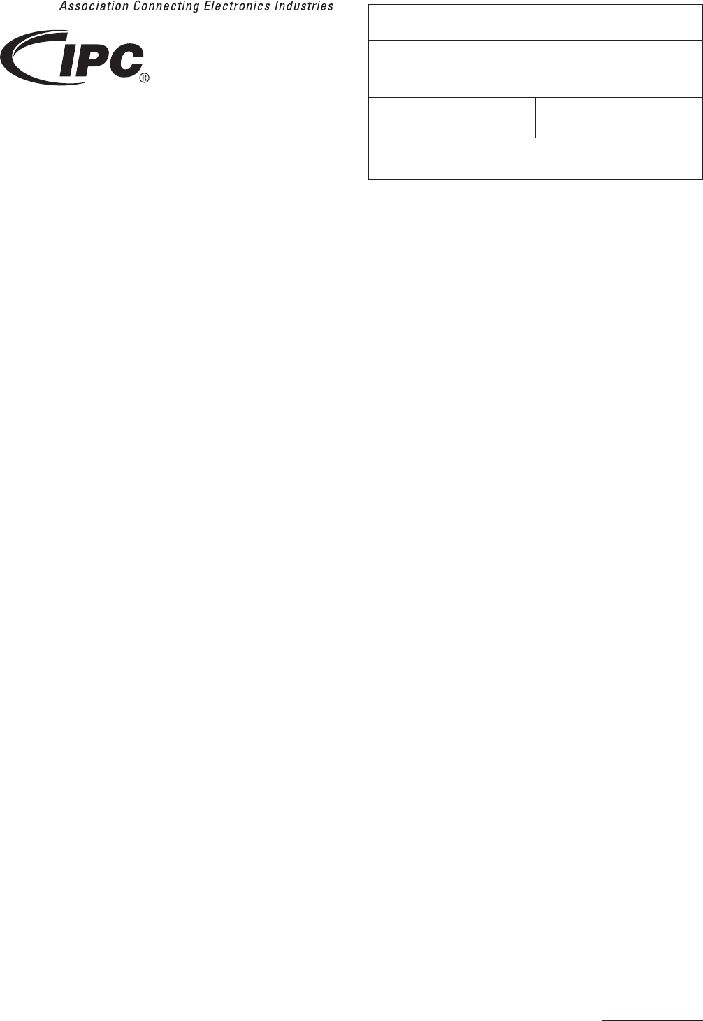
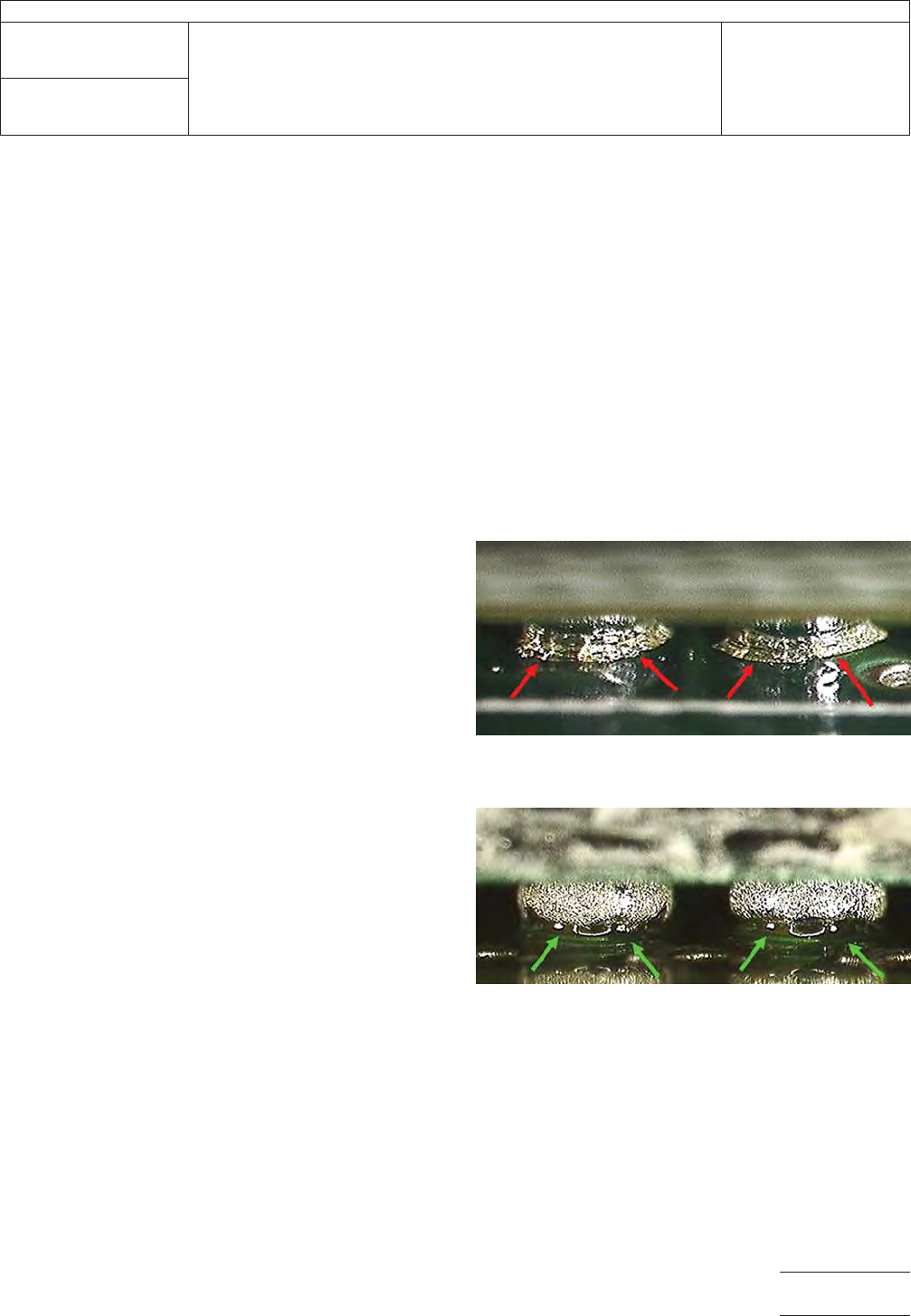
5.2.1 The initial visual examination is used to detect signs of
mechanical damage/stress. If flux is present, examine for
fractured/broken-up or disturbed flux around the SMT solder
joints (see Figure 1 and Figure 2).
5.2.2 If the SMT part required the use of corner-applied
adhesive and the adhesive is visible, examine and document
it per customer requirements to determine if dye and pull test-
ing is applicable. See IPC-7095 for additional guidance on the
proper use of corner-applied adhesive.
5.3 If the part has a heatsink, package metal heat spreader
or any other assembly that is attached, proceed as follows to
avoid inducing any mechanical stress into the solder joint.
5.3.1 Remove the heatsink. If there is any concern with the
proper method to remove an attached heatsink, it is highly
recommended that it be left in place until after the dye-drying
step (5.11).
3000 Lakeside Drive, Suite 105N
Bannockburn, IL 60015-1249
IPC-TM-650
TEST METHODS MANUAL
Number
2.4.53
Subject
Dye and Pull Test Method (Formerly Known as Dye
and Pry)
Date
8/2017
Revision
Originating Task Group
Bottom Termination Components (5-22k)
Material in this Test Methods Manual was voluntarily established by Technical Committees of IPC. This material is advisory only
and its use or adaptation is entirely voluntary. IPC disclaims all liability of any kind as to the use, application, or adaptation of this
material. Users are also wholly responsible for protecting themselves against all claims or liabilities for patent infringement.
Equipment referenced is for the convenience of the user and does not imply endorsement by IPC.
Page1of11

5.3.2 If there is a metal heat spreader on the BGA, it must
be left in place until after the dye-drying step (5.11).
5.4 Section out the desired component area leaving about
19 mm to 38 mm [0.75 in to 1.5 in] of board around the part.
If the board is small enough to fit the pull fixture, leave the
board intact.
5.4.1 A diamond sectioning saw is recommended to per-
form this step. Other sectioning equipment (e.g., diamond
saw, milling tool, water jet, etc.) can be used if it does not
induce stress on the sample area.
5.5 A detailed visual examination under stereomicroscope is
required at this stage. If needed, clean the sectioned part with
only water and compressed air. It is important to not use sol-
vent for this step.
5.5.1 A thorough visual examination can detect signs of
mechanical damage/stress, which are indicated by fractured/
broken-up flux around the SMT solder joint (see Figure 1 and
Figure 2).
5.5.2 If the SMT part utilizes corner-applied adhesive which
was not easily visible before, examine it now. Document the
glue coverage per IPC-7095 or as determined between the
lab and the customer.
5.5.3 Document the findings in lab notes and with photos.
5.6 Clean any flux residue from around the SMT solder joints
using the appropriate flux remover.
Note: Isopropyl alcohol is not acceptable due to its inability to
dissolve flux.
5.6.1 The sectioned part/board area should be submerged
in liquid flux remover for at least one hour. The goal is to fully
remove the flux residue. The exact amount of time the part/
board is submerged depends on the sample conditions.
5.6.1.1 Approximately two to three times during soak, gen-
tly swirl the beaker containing the sectioned part for at least
20 seconds. This will aid the flux solvent in removing the flux
ring residue.
5.6.2 Reworked samples may require additional time in the
liquid flux remover.
5.6.3 Examine the sample under a microscope to determine
if additional time is needed to remove the flux ring.
5.6.4 After using the liquid flux remover, use a spray can flux
remover to thoroughly flush all four sides of the component.
5.6.4.1 Removing all flux residues and other particles/oils
enables the dye to penetrate the fractures.
5.6.4.2 Failure to completely remove the flux from around
the solder joint will prevent dye penetration and give false indi-
cations of a good solder joint.
5.7 Use low-pressure compressed air to blow off excess flux
solvent.
5.7.1 If desired, perform a final rinse with isopropyl alcohol
or acetone at this time.
5.8 Pour the dye into a small tray until the sectioned sample
is completely immersed in the dye.
5.8.1 If dye is being reused, ensure it has sufficient viscos-
ity. Viscosity is critical to the ability of the dye to penetrate into
cracks within the parts being dyed. If there are any concerns
with dye viscosity, discard the old dye and use fresh, new
dye.
5.9 Place the tray containing the sectioned sample into a
vacuum chamber.
5.9.1 Draw a 67.7 kPa [20 in Hg] vacuum for three to four
minutes.
5.9.2 Partially vent and then reapply vacuum to the chamber
to aid in dye penetration.
5.9.3 Leave the part submerged in dye for a minimum of 30
minutes with a constant vacuum of 67.7 kPa [20 in Hg].
5.9.3.1 Do not exceed 67.7 kPa [20 in Hg] of vacuum at any
time, or the dye will start to boil off.
5.10 Vent the vacuum chamber slowly and remove the
sample from the tray.
5.10.1 Allow the excess dye to drain off the sample.
IPC-TM-650
Number
2.4.53
Subject
Dye and Pull Test Method (Formerly Known as Dye and Pry)
Date
8/2017
Revision
Page2of11
5.10.2 Use low-pressure compressed or canned air to gen-
tly flush any remaining dye from under the part until no further
dye runs out.
5.10.3 Dry the sample in an oven, not to exceed 100 °C or
as appropriate for the sample. If possible, allow the part to dry
overnight at ambient conditions. Wet dye can smear during
component separation, resulting in false conclusions.
5.11 Remove the sectioned part from the oven and allow it
to cool.
5.12 Perform the pull operation to physically/mechanically
remove the part from the board.
5.12.1 Abrade the surface to allow for an improved bonding
of the structural adhesive.
Example: One way to perform this is to use a small piece of
coarse-grit sandpaper to lightly sand and roughen the part top
surface. This will remove the dried dye and will allow the top
surface to bond with the anchored tee nut.
5.12.2 Bond the tee nut to the top of the part using struc-
tural adhesive. Allow the structural adhesive to cure.
5.12.3 Use a pull-test fixture with a uniform tensile force to
separate the part from the board.
5.13 Examine the board and component for dye indications.
If necessary, gently dust with canned air or dry, filtered and
regulated compressed air to the separated part to clear away
pull debris (flakes of dye, solder mask, etc.).
5.13.1 Any fractured interface that was present will be
stained with dye. Usually, both sides are stained in a common
(mirrored) pattern.
5.14 Take photos of dyed regions and plot results as agreed
upon between the lab and the customer.
5.15 Test Report Include the following (or as agreed upon
between the lab and the customer):
• Initial visual observations (see 5.2 and 5.5)
• Dyed interface separation location
• If required, dye indication amount/percentage (acceptability
criteria to be determined between laboratory and customer)
Other items that can be included in the test report include:
• Mapping of all separation locations
6 Notes/Figures
The figures in this section are included for informational pur-
poses only. They do not depict a correct or incorrect method
for conducting this test method.
Figure 1 Ball Grid Array (BGA) With Disturbed Flux,
Indicating Possible Solder or Laminate Fractures
Figure 2 Ball Grid Array (BGA) Without Disturbed Flux
IPC-TM-650
Number
2.4.53
Subject
Dye and Pull Test Method (Formerly Known as Dye and Pry)
Date
8/2017
Revision
Page3of11