IPC-TM-650 EN 2022 试验方法.pdf - 第688页
1.0 Scope The purpose of this method is to determine the physical endurance of printed boards to sudden exposure to extreme changes in temperature and the effect of alternate exposures to these extremes. The exposure of …
1.0
Scope
This
test is conducted for the purpose of deter-
mining the resistance of a material such as a laminate or mul-
tilayer circuit board, to the shock of repeated exposures to
extremes of high and low temperatures for comparatively
short periods of time.
2.0
Applicable documents
None
3.0
Test specimen
The
test specimen for this test shall be
a sheet of laminate material at least 6 inch x 6 inch by the
thickness of the laminate. In the case of multilayer boards, the
test specimen shall be the entire qualification specimen
detailed in part 5.8.4 of this publication.
4.0
Apparatus
A
chamber automatic temperature cycling
equipment suitable for the temperature extremes specified
herein. The air temperature shall be maintained by forced air
circulation. The chamber shall have sufficient heating or cool-
ing capacity to maintain the specified air temperature.
5.0
Procedure
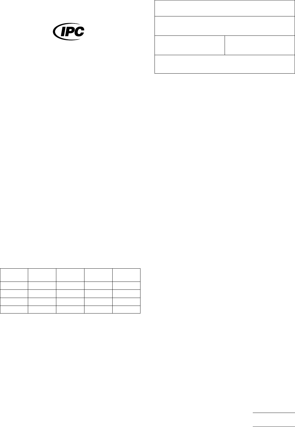
5.1 Conditions
During
the exposures, maintain the cham-
ber at the temperatures shown below:
Class
A Class B
Step
T
emp.
(°C)
Time
(Min.)
Temp.
(°C)
Time
(Min.)
1 125+3/–0 30 85+3/–0 30
2 25+10/–5 10–15 25+10/–5 10–15
3 –65+0/–5 30 –55+0/–5 30
4 25+10/–5 10–15 25+10/–5 10–15
5.2 Preparation
The
test specimen must be cleaned of
dirt, grease, and other contaminants prior to the thermal
exposure. The test specimen should be cleaned by wiping
with a dry, clean lint-free cloth, or wiped with a clean lint-free
cloth dampened with acetone or isopropyl alcohol. The speci-
men must be allowed to air dry prior to thermal exposure.
5.3
Test exposure
The
test specimen must be placed in
the thermal chamber maintained at the temperature specified
in Step 1 for the appropriate test condition. The test specimen
must be maintained at each temperature in the order speci-
fied. Throughout the test, the specimen must be placed in
such a position so that there is essentially no obstruction to
the flow of air around them. The specimen should be sub-
jected to the specified temperatures in the sequence specified
for a total of five cycles performed continuously.
5.4
Upon
copulation of the five temperature cycles, allow
the specimen to return to room temperature. Visually inspect
the specimen in accordance with detailed requirements.
The
Institute for Interconnecting and Packaging Electronic Circuits
2215 Sanders Road • Northbrook, IL 60062-6135
IPC-TM-650
TEST
METHODS MANUAL
Number
2.6.6
Subject
Temperature
Cycling, Printed Wiring Board
Date
12/87
Revision
B
Originating Task Group
N/A
Material
in this Test Methods Manual was voluntarily established by Technical Committees of the IPC. This material is advisory only
and its use or adaptation is entirely voluntary. IPC disclaims all liability of any kind as to the use, application, or adaptation of this
material. Users are also wholly responsible for protecting themselves against all claims or liabilities for patent infringement.
Equipment referenced is for the convenience of the user and does not imply endorsement by the IPC.
P
age1of1
电子技术应用 www.ChinaAET.com

1.0
Scope
The
purpose of this method is to determine the
physical endurance of printed boards to sudden exposure to
extreme changes in temperature and the effect of alternate
exposures to these extremes. The exposure of the printed
board specimens to the high and low temperature extremes is
designed to cause physical damage, deterioration, or signifi-
cant changes in resistance.
2.0
Applicable Documents
IPC-D-275
Design
Standard for Rigid Printed Boards and
Rigid Printed Board Assemblies.
3.0
Test Specimen
Test
coupon ‘‘D’’ from IPC-D-275 or
other suitable test coupon (see 6.1a).
4.0
Apparatus
4.1
An
automatically controlled dual temperature environ-
mental test chamber or other dual chamber apparatus
capable of maintaining –65, –55, –40 or 0°C+0–5°C [–85,
–67, –40, +32°F+0–9°F] in the low temperature chamber
and 70, 85, 105, 125, 150 or 170 +5 –0°C [158, 185, 221,
257, 302 or 338° F+9–0°F] in the high temperature chamber.
NOTE: The temperature extremes (high and low) that are
required is dependent on the base material of the specimen
that is to be tested (see 6.1b ). The recovery capacity of the
test chambers shall be such that the internal chamber air tem-
perature shall reach the specified temperature within 2 min-
utes after the specimen(s) have been transferred to the test
chamber.
4.2
An
electrical resistance meter capable of accuracies of
0.5 milliohm or better with Kelvin (4 terminal) type leads. A
Kelvin type double bridge or potentiometer of the specified
accuracy may also be used (see 6.2).
5.1
Preparation
Wire
up test specimen with Kelvin-type
leads at the points where measurements will be made.
5.1.1
Operate
chamber (or chambers) and allow to stabilize
at the high and low temperature required. Clamp or suspend
specimen in the approximate center of the high temperature
chamber. First specimens shall be placed approximately 13
mm [0.5 in] apart and aligned in a manner to permit maximum
heat transfer to the test specimen(s).
5.2
Test
5.2.1 Thermal Shock Cycle
5.2.1.1
The
specimens shall be subjected to 100 tempera-
ture cycles in accordance with the applicable test condition of
Table 1.
5.2.1.2
Transfer
time between chambers shall be less than
2 minutes. The thermal capacity of the test chamber used
shall be such that the ambient temperature shall reach the
specified temperature within 2 minutes after the specimen has
been transferred to the appropriate chamber.
5.2.1.3
Interconnection
resistance measurements shall be
taken before the test, during the first cycle at high tempera-
ture, and during the last cycle at high temperature. In-cham-
ber resistance measurements should be taken during the last
few minutes of chamber exposure. Care should also be taken
to measure samples after approximately the same duration at
chamber temperature.
5.3
Evaluation
The
maximum change in resistance
between the first and 100th cycle shall be evaluated for
acceptability to the requirements of the applicable specifica-
tion.
6.0 Notes
6.1
The
following details are to be specified in the applicable
performance specification:
a. Test specimen, if other than specified in 3.0.
b. Test condition, if other than specified in 4.1.
c. Maximum change in resistance.
The
Institute for Interconnecting and Packaging Electronic Circuits
2215 Sanders Road • Northbrook, IL 60062-6135
IPC-TM-650
TEST
METHODS MANUAL
Number
2.6.7
Subject
Thermal
Shock & Continuity, Printed Board
Date
8/97
Revision
A
Originating Task Group
Rigid Board T.M. Task Group, 7-11d
Material
in this Test Methods Manual was voluntarily established by Technical Committees of the IPC. This material is advisory only
and its use or adaptation is entirely voluntary. IPC disclaims all liability of any kind as to the use, application, or adaptation of this
material. Users are also wholly responsible for protecting themselves against all claims or liabilities for patent infringement.
Equipment referenced is for the convenience of the user and does not imply endorsement by the IPC.
P
age1of2
电子技术应用 www.ChinaAET.com
6.1.1
Unless
otherwise specified by the applicable perfor-
mance specification, the following base material types/
temperature ratings are recommended.
6.2
Suggested sources for capable test equipment:
Cambridge
Technology
Model 510A Micro-Ohmmeter
23 Elm Street
Watertown, MA 02172
(617) 923-1181
Hewlett-Packard
Model 4338A Milliohmmeter
9800 Muirlands Avenue
Irvine, CA 92718
(714) 472-3000
Keithly Instruments
Model 580
Micro-ohmmeter
28775 Aurora Road
Cleveland, OH 44139
(800) 552-1115
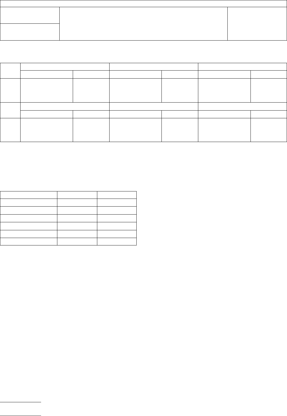
T
able 1
Step
T
est Condition A Test Condition B Test Condition C
Temperature Time Temperature Time Temperature Time
1
2
3
4
0, +0/-5
25, +10/-5
+70, +5/-0
25, +10/-5
15
0
15
0
-40, +0/-5
25, +10/-5
+85, +5/-0
25, +10/-5
15
0
15
0
-55, +0/-5
25, +10/-5
+105, +5/-0
25, +10/-5
15
0
15
0
Step
Test Condition D Test Condition E Test Condition F
Temperature Time Temperature Time Temperature Time
1
2
3
4
-55, +0/-5
25, +10/-5
+125, +5/-0
25, +10/-5
15
0
15
0
-65, +0/-5
25, +10/-5
+150, +5/-0
25, +10/-5
15
0
15
0
-65, +0/-5
25, +10/-5
+170, +5/-0
25, +10/-5
15
0
15
0
T
olerance shall be +2 and -0 minutes.
T
able 2
Rigid
Type NEMA Test Condition
A
GP, GT, GX, GY B
GE C
AF, BF, BI, CF, GF, GB D
GH, GM E
AI, GI, QI F
IPC-TM-650
Number
2.6.7
Subject
Thermal
Shock & Continuity, Printed Board
Date
8/97
Revision
A
P
age2of2
电子技术应用 www.ChinaAET.com