IPC-TM-650 EN 2022 试验方法.pdf - 第547页
5.4.1 Measure the length L of each of the two split-cylinder resonator sections over several locations and compute the mean length of both sections. 5.4.2 With the split-cylinder empty (no substrate) and closed (d=0), fi…
4 Measurement Apparatus
4.1 Split-Cylinder Resonator
The method employs a
split-cylinder resonator, which is a cylindrical cavity separated
into two halves of equal length, with a dielectric substrate
placed in the gap between the two cavity sections. The split-
cylinder resonator must be constructed to allow an adjustable,
variable gap between the two cavity sections for introduction
of the dielectric substrate. Additional details about the con-
struction of a split-post resonator are given in the references
described in 6.2. Over the years there have been commercial
manufacturers of this fixture.
In order to excite and detect the desired fundamental TE
011
resonant mode in the split-cylinder resonator, a coupling loop
is introduced, through a small hole in the cavity wall, in each
of the two cavity regions. The plane of the coupling loop
should be parallel to the plane of the sample, in order to allow
maximum interaction with the vertical component of the mag-
netic field. Each of the coupling loops is connected to a
coaxial transmission line that is connected to the input port of
a network analyzer. To minimize the effect of coupling losses,
the distance to which the loops extend radially into each of the
cavity sections must also be adjustable. In addition to the fun-
damental TE
011
mode, higher modes can be used to extend
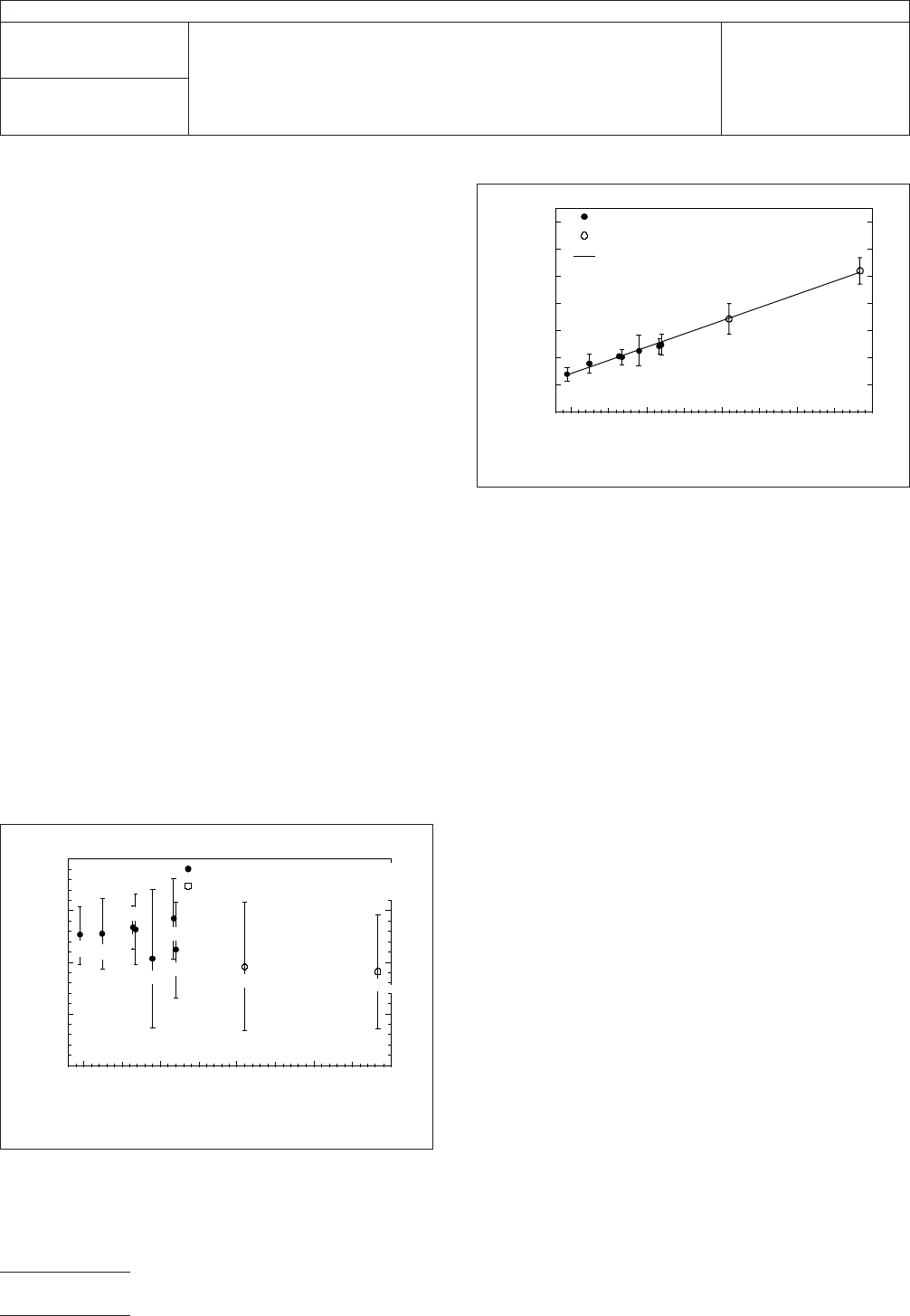
the measurement frequency. Typical measurements on fused
silica with higher mode measurements are shown in Figures 3
and 4.
4.2 Network Analyzer A scalar or vector network analyzer
is necessary to perform the measurement with the split-
cylinder resonator. Commercially available network analyzers
operate over various frequency ranges, so care is needed to
ensure that the network analyzer covers the necessary fre-
quency range for the particular split-cylinder resonator used.
4.3 Digital Micrometer The dielectric substrate thickness
can be measured with a digital micrometer with a minimal
resolution of 0.001 mm [0.000039 in].
5 Procedure
5.1
Turn on the network analyzer and allow the unit to
warm-up and stabilize according to the manufacturer’s
instructions.
5.2 Connect the network analyzer’s two input ports to the
split-cylinder resonator’s coupling loops using coaxial trans-
mission lines.
5.3 Measure the thickness of the substrate over several
locations using a digital micrometer, and compute the mean
substrate thickness.
5.4 Determine split-cylinder resonator properties. The
length, radius and conductivity of the split-cylinder resonator
must be known before the substrate relative permittivity and
loss tangent can be calculated. If these variables have not
been already determined, the following procedure can be
used:
IPC-25513-3
Figure 3 Typical Measurements of the Real Part of
the Permittivity using 10 GHz and 35 GHz Split-cylinder
Resonators including Measurements with Higher Modes
3.90
10 20
Frequency (GHz)
30 40 50
3.85
3.80
3.75
3.70
Relative Permittivity
10 GHz Split-Cylinder Resonator
35 GHz Split-Cylinder Resonator
TE
011
TE
013
TE
021
TE
023
TE
017
TE
025
TE
011
TE
013
TE
015
IPC-25513-4
Figure 4 Typical Measurements of the Loss-tangent
using 10 GHz and 35 GHz Split-cylinder Resonators
including Measurements with Higher Modes
7x10
-4
6
5
4
3
2
1
0
10 20
Frequency (GHz)
30 40 50
Loss Tangent
35 GHz Split-Cylinder Resonator
Linear Least Squares Fit
10 GHz Split-Cylinder Resonator
TE
011
TE
013
TE
021
TE
023
TE
017
TE
025
TE
011
TE
013
TE
015
IPC-TM-650
Number
2.5.5.13
Subject
Relative Permittivity and Loss Tangent Using a Split-Cylinder
Resonator
Date
01/07
Revision
Page2of4
5.4.1 Measure the length L of each of the two split-cylinder
resonator sections over several locations and compute the
mean length of both sections.
5.4.2 With the split-cylinder empty (no substrate) and closed
(d=0), find the TE
011
resonance with the network analyzer.
To reduce the coupling losses to a negligible level, adjust
the radial position of the coupling loops so that the peak of
the resonance curve is less than -40 dB. For the particular
10 GHz split-cylinder resonator described in this method, the
resonant frequency should be approximately 10.04 GHz. If
another split-cylinder geometry is being used, use the follow-
ing approximation to estimate the TE
011
resonant frequency of
an empty split-cylinder resonator:
ƒ
011
=
c
2π
√
(
j
1
a
)
2
+
(
π
2L
)
2
where c is the speed of light in a vacuum, j
1
is the first zero of
the Bessel function of the first kind J
1
, a is the split-cylinder
radius in meters and L is the length, in meters, of each of the
split-cylinder sections as shown in Figure 2.
5.4.3 Once the TE
011
resonance has been identified and
displayed on the network analyzer display, measure the reso-
nant frequency f
011
and quality factor Q of the resonance and
use the following expressions to compute the radius a and the
conductivity σ of the empty split-cylinder’s resonator sections:
a=j
1
[
(
2πƒ
011
c
)
2
−
(
π
2L
)
2
]
−
1
2
σ=
2πƒ
011
µ
0
2R
s
2
where µ
0
is the permeability of free space and
√
µ
0
ε
0
[
(
j
1
a
)
2
+
(
π
2L
)
2
]
3
2
R
s
=
2Q
[
1
2L
(
π
2L
)
2
+
1
a
(
j
1
a
)
2
]
5.5 Estimate the TE
011
Resonant Frequency of
Substrate-Loaded Split-Cylinder Resonator
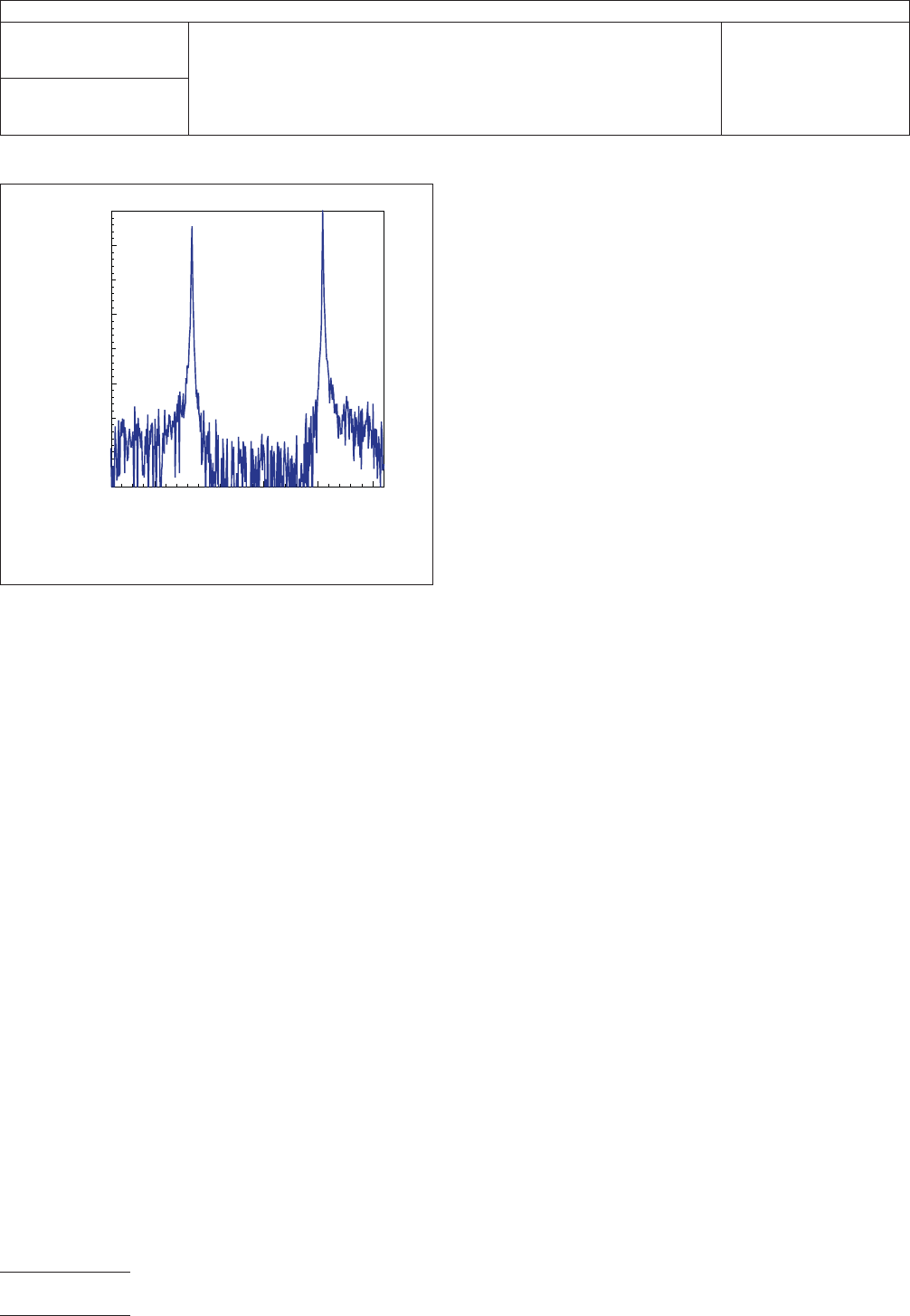
In addition
to the desired TE
011
resonant mode, other modes are excited
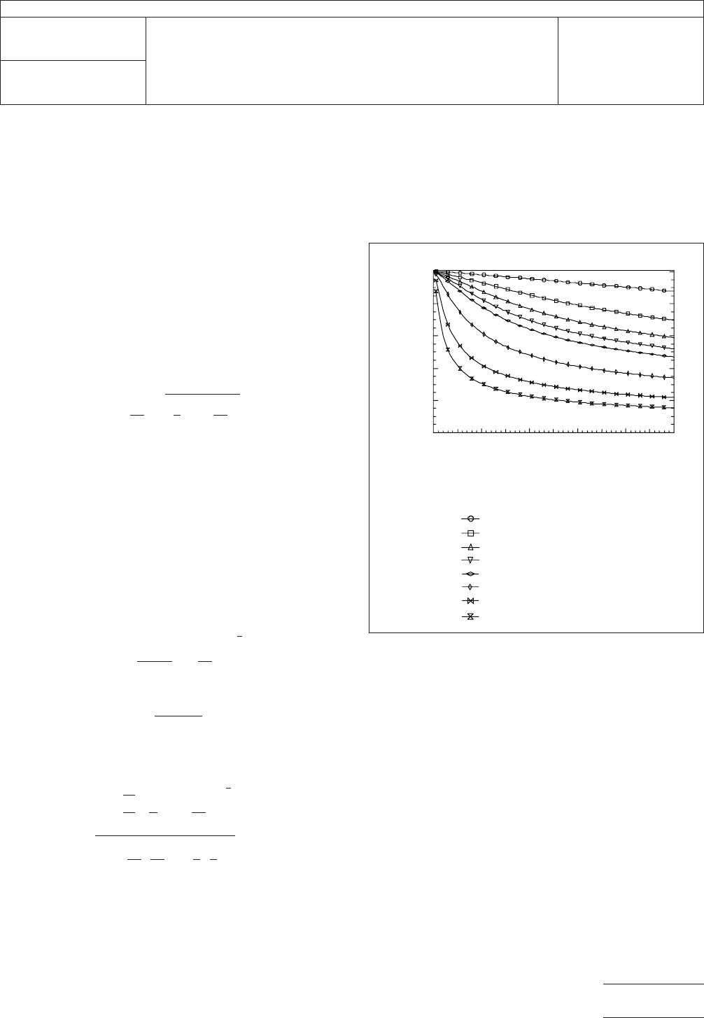
in the split-cylinder resonator as shown in Figure 5. Depend-
ing on the thickness and relative permittivity of the dielectric
substrate being measured, the resonant frequency for the
split-cylinder plus substrate can be significantly lower than the
resonant frequency of the empty split-cylinder resonator as
shown in Figure 6.
In order to identify the correct mode, one can use Figure 6 to
predict the resonant frequency of the TE
011
resonant mode.
For a more accurate estimate of this resonant frequency and
the frequencies of the higher-order resonant modes, software
is available from the National Institute of Standards and Tech-
nology (NIST) which calculates the split-cylinder resonator
dimensions, substrate thickness, and provides an estimate of
the relative permittivity of the substrate. As of the publication
of this method, additional commercial vendors are developing
similar software and will be listed through the IPC-TM-650
Test Methods web page.
5.6 Measure the Relative Permittivity and Loss Tangent
5.6.1
Place the substrate in the gap separating the two cav-
ity sections of the split-cylinder resonator in such a way that
IPC-25513-5
Figure 5 Frequency of the TE
011
Resonant Mode as a
Function of Permittivity and Substrate Thickness for
the 10 GHz Split-Cylinder Resonator
Substrate Thickness (mm)
Sample Relative Permittivity
2
4
6
8
10
20
50
100
10
8
6
4
2
0
01234
5
TE
011
Resonant Frequency (GHz)
IPC-TM-650
Number
2.5.5.13
Subject
Relative Permittivity and Loss Tangent Using a Split-Cylinder
Resonator
Date
01/07
Revision
Page3of4
the substrate extends beyond the circumference of both cav-
ity sections. Adjust the separation of the two resonator sec-
tions so that the substrate is held by the weight of the upper
cavity between the two cavity sections.
5.6.2 Using the estimate calculated in 5.3, measure the
resonant frequency and quality factor of the TE
011
resonant
mode using the network analyzer. Since the split-cylinder
resonator is a two-port cavity, the network analyzer should be
set to measure S
21
, the scattering parameter that measures
the transmission through the cavity. The resonance may have
a significant amount of noise, so it may be necessary to adjust
the amount of averaging performed by the network analyzer.
In some cases where the resonance curve is near the noise
floor, increasing the coupling level of the split-cylinder resona-
tor may be necessary to improve the signal to noise level,
although this may introduce a small amount of coupling loss.
5.6.3 When using the available software, the routine will cal-
culate the relative permittivity and loss tangent of the dielectric
substrate after properly identifying the TE
011
resonant mode.
These values are displayed in the software front panel, includ-
ing an estimate of the measurement uncertainties for the rela-
tive permittivity and loss tangent.
6 Notes If additional measurements are needed at higher
frequencies, the available software will provide the frequencies
of the higher-order TE
0np
resonant modes. The user must
ensure that these modes are symmetric and not distorted by
adjacent resonant modes.
The uncertainties in the real part and loss tangent measure-
ment will be calculated automatically from the uncertainties in
various dimensions that are specified. The major source of
uncertainty will be the uncertainty in the substrate thickness.
Note that the electric field of the TE
011
resonant mode is in the
plane of the substrate. Therefore, if the substrate is anisotro-
pic, the measured component of the relative permittivity also
is in the plane of the substrate.
6.1 Software Availability Software may be available from
commercial vendors and in addition executable code is avail-
able from the Electromagnetic Properties of Materials Project
at the National Institute of Standards and Technology (NIST,
Boulder, CO). As commercial vendor software becomes avail-
able, IPC will provide listings for these at the IPC-TM-650 web
page located at www.ipc.org, under ‘‘Standards.’’
6.2 References
M.D. Janezic, ‘‘Nondestructive Relative Permittivity and Loss
Tangent Measurements using a Split-Cylinder Resonator,’’
Ph.D. Thesis, University of Colorado at Boulder, 2003.
M.D. Janezic, E.F. Kuester, J. Baker-Jarvis, ‘‘Broadband
Complex Permittivity Measurements of Dielectric Substrates
using a Split-Cylinder Resonator,’’ IEEE MTT-S International
Microwave Symposium Digest, pp. 1817-1820, 2004.
M.D. Janezic and J. Baker-Jarvis, ‘‘Full-Wave Analysis of a
Split-Cylinder Resonator for Nondestructive Permittivity Mea-
surements,’’ IEEE Transactions on Microwave Theory and
Techniques, vol. 47, no. 10, pp. 2014-2020, 1999.
K.J. Coakley, J.D. Splett, M.D. Janezic, R.F. Kaiser, ‘‘Estima-
tion of Q-factors and resonant frequencies,’’ IEEE Transac-
tions on Microwave Theory and Techniques, vol. 51, no. 3,
pp. 862-868, 2003.
J. Baker-Jarvis et al, ‘‘Dielectric and Conductor Measure-
ments of Electronic Packaging Materials,’’ NIST Technical
Note 1520, 2001.
J. Baker-Jarvis et al, ‘‘Measuring the permittivity and perme-
ability of lossy materials: solids, liquids, building materials, and
negative-index materials,’’ NIST Technical Note 1536, 2005.
B.N. Taylor, ‘‘Guidelines for Expressing the Uncertainties of
NIST Measurement Results,’’ NIST Technical Note 1297,
1994.
IPC-25513-6
Figure 6 Typical Multiple Split-Cylinder Resonator
Resonances
Frequency (GHz)
-60
-70
-80
-90
8.6 8.7 8.8 8.9 9.0
Magnitude of S
21
(dB)
IPC-TM-650
Number
2.5.5.13
Subject
Relative Permittivity and Loss Tangent Using a Split-Cylinder
Resonator
Date
01/07
Revision
Page4of4