IPC-TM-650 EN 2022 试验方法.pdf - 第263页
4.4 Solder Pot An electrically-heated, thermostatically con- trolled solder pot of adequate dimensions to accommodate the specimen and contain no less than 2.25 Kg [5 pounds] of SN60 solder. 4.5 Automatic Temperature Cyc…
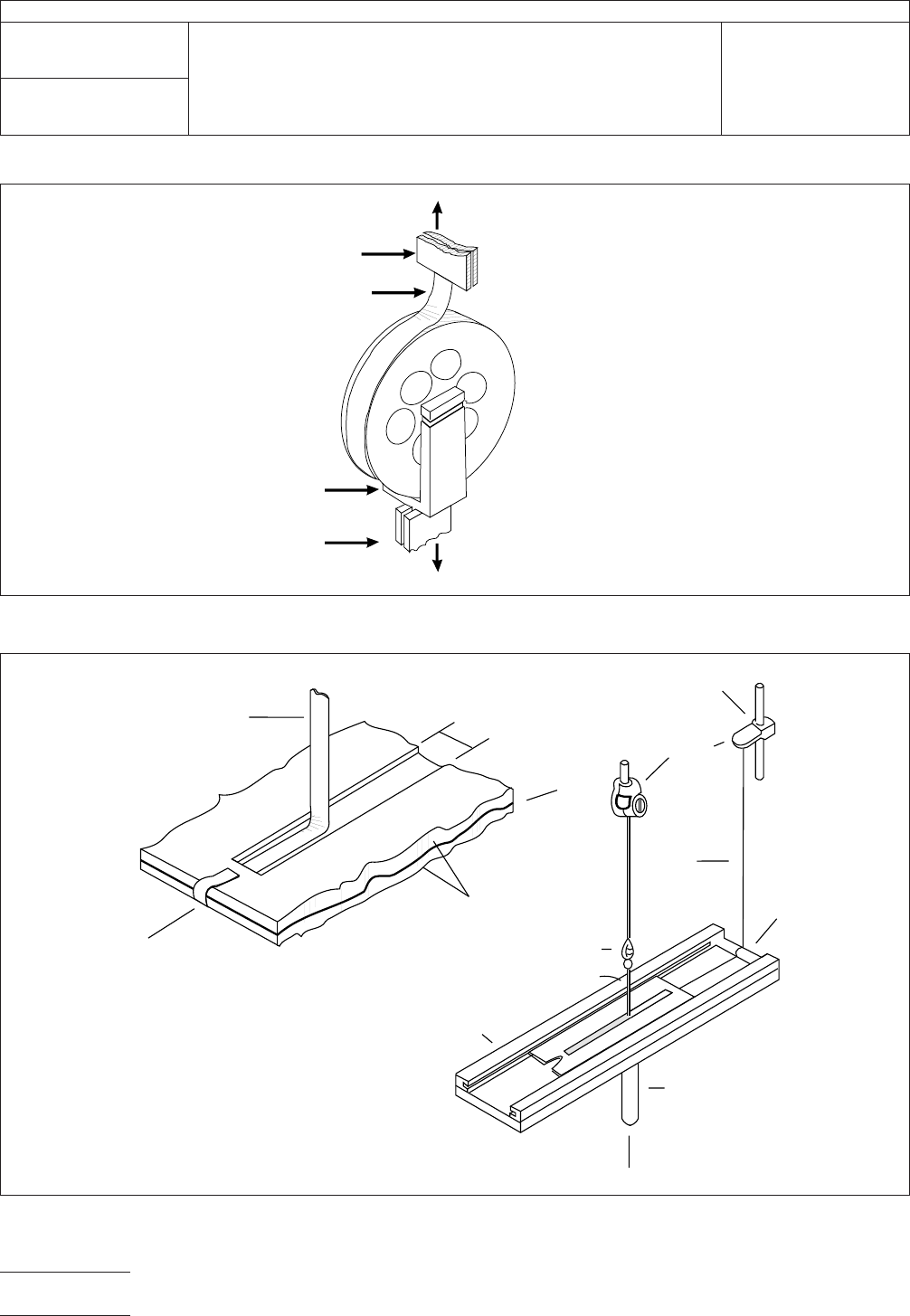
IPC-249-2
Figure 2 Free Wheeling Rotary Drum Test Fixture
6 Inch Diameter
Testing
Machine
Specimen
Testing
Fixture
Testing
Machine
IPC-249-3
Figure 3 Sliding Plate Test Fixture
▼
▼
▼
▼
▼
▼
Specimen
.150"
Specimen Holders
Clip for
Fastening Cord
Conductor
▼
Test bed with machined grooves
to permit free movement of
specimen holders
Testing
Machine
Pulley
Clasp
Conductor
Wire
Cord
Yoke
Testing
Machine
▼
▼
▼
▼
▼
▼
▼
▼
▼
▼
IPC-TM-650
Number
2.4.9
Subject
Peel Strength, Flexible Dielectric Materials
Date
04/14
Revision
E
Page2of6

4.4 Solder Pot An electrically-heated, thermostatically con-
trolled solder pot of adequate dimensions to accommodate
the specimen and contain no less than 2.25 Kg [5 pounds] of
SN60 solder.
4.5 Automatic Temperature Cycling Chamber (See
5.5.3.)
5 Procedure
5.1 MethodA–AsReceived – Etched Specimen
5.1.1
Prepare Type A etched conductor test specimens in
accordance with Figure 1 using standard commercial prac-
tices per 3.1.2.
5.1.2 Condition specimens for 24 hours at 23 °C±2°C
[73.4 °F ± 3.6 °F] and 50% ± 5% relative humidity. Stabiliza-
tion time may be reduced if statistically sound evidence has
been generated on the specific product line to support the
shorter stabilization times.
5.1.3 Attach the specimen to the test fixture with double-
sided tape, cement, and/or mechanical clamps. The referee
attachment technique will be double sided adhesive tape.
5.1.4 Peel the conductor at a rate (crosshead speed) of
50.8 mm/minute [2 in/minute]. The peel load shall fall within
15% to 85% of the range of the scale used on the testing
machine. The peel load shall be continuously recorded, and
the recorded load for the entire length of the peeled conduc-
tor shall be evaluated per 5.7.1. A minimum of 57.2 mm
[2-1/4 in] must be peeled, the first 6.4 mm [1/4 in] to be dis-
regarded.
5.2 MethodB–AsReceived – Die Cut Specimen
5.2.1
Cut Type B test specimens with the Thwing Albert
sample cutter per 3.2.2.
5.2.2 Condition specimens for 24 hours at 23 °C±2°C
[73.4 °F ± 3.6 °F] and 50% ± 5% relative humidity. Stabiliza-
tion times may be reduced if statistically sound evidence has
been generated on the specific product line to support the
shorter stabilization times.
5.2.3 Attach the specimen to the test fixture with double-
sided tape, cement, and/or mechanical clamps. The referee
attachment technique will be double sided adhesive tape.
5.2.4 Peel the foil at a rate (crosshead speed) of 50.8 mm/
minute [2 in/minute]. The peel load shall fall within 15%
to 85% of the range of the scale used on the testing machine.
The peel load shall be continuously recorded, and the
recorded load for the entire length of the peeled conductor
shall be evaluated per 5.71. A minimum of 57.2 mm [2-1/4 in]
must be peeled, the first 6.4 mm [1/4 in] to be disregarded.
5.3 Method C – Solder Float – Etched Specimen
5.3.1
Prepare Type A etched conductor test specimen in
accordance with Figure 1 using standard commercial prac-
tices per 3.2.1.
5.3.2 Dry the test specimens in an area circulating oven
maintained at 135 °C ± 10 °C [275 °F ± 18 °F] for one hour.
5.3.3 Remove the specimen from the conditioning chamber,
apply solder stop (e.g., petroleum jelly) to the conductor side
and float each specimen, conductor side down, just beneath
the surface of molten solder at 288 °C±6°C[550 °F ± 10 °F]
for at least five seconds. A solder float test fixture that keeps
the test specimen flat and just below the solder surface shall
be used. Agitate the specimen from side to side during
immersion, then remove the specimen and tap the edge to
remove excess solder. Suitable procedures shall be used to
ensure that solder does not remain on test specimen.
5.3.4 Repeat steps 5.1.2 through 5.1.4 as performed in
Method A.
5.4 Method D – Solder Float – Die Cut Specimen
5.4.1
Cut Type B test specimens with the Thwing Albert
sample cutter per 3.2.1.
5.4.2 Dry the test specimens in an air circulating oven main-
tained at 135 °C ± 10 °C [275 °F ± 18 °F] for one hour.
5.4.3 Remove the specimen from the conditioning chamber,
apply solder stop (e.g., petroleum jelly) and float each speci-
men, conductor side down, just beneath the surface of mol-
ten solder at 288 °C±6°C[550 °F ± 10 °F] for at least five
seconds. A solder float test fixture that keeps the test
specimen flat and just below the solder surface shall be used.
Agitate the specimen from side to side during immersion, then
remove the specimen and tap the edge to remove excess
solder. Suitable procedures shall be used to ensure that sol-
der does not remain on test specimen.
IPC-TM-650
Number
2.4.9
Subject
Peel Strength, Flexible Dielectric Materials
Date
04/14
Revision
E
Page3of6

5.4.4 Repeat steps 5.2.2 through Method B.
5.5 Method E – After Aging Etched Specimen
5.5.1
Prepare Type A etched conductor test specimen in
accordance with Figure 1 using standard commercial prac-
tices per 3.1.1.
5.5.2 Condition specimens for 24 hours at 23 °C±2°C
[73.4 °F ± 3.6 °F] and 50% ± 5% relative humidity. Stabiliza-
tion time may be reduced if statistically sound evidence has
been generated on the specific product line to support the
shorter stabilization times.
5.5.3 Expose each test specimen to five cycles at the time-
temperature sequence: 30 minutes +1/-0 minutes at 150 °C
+5 °C/-0 °C [302 °F +9 °F/-0 °F]; 15 minutes +1/-0 minutes
at 23 °C ± 10 °C [73.4 °F ± 18 °F]; 30 minutes +1/-0 minutes
at -55 °C +0 °C /-5 °C [-67 °F -9 °F/+0 °F]; 15 minutes +1/-0
minutes at 23 °C ± 10 °C [73.4 °F ± 18 °F].
5.5.4 Repeat steps 5.1.2 through 5.1.4 as performed in
Method A.
5.6 Method F – After aging – Die Cut Specimen
5.6.1
Cut Type B test specimens with the Thwing Albert
sample cutter per 3.2.1.
5.6.2 Condition specimens for 24 hours at 23 °C±2°C
(73.4 °F ± 3.6 °F) and 50% ± 5% relative humidity. Stabiliza-
tion time may be reduced if statistically sound evidence has
been generated on the specific product line to support the
shorter stabilization times.
5.6.3 Expose each test specimen to five cycles at the time-
temperature sequence: 30 minutes +1/-0 minutes at 150 °C
+5 °C/-0 °C [302 °F +9 °F/-0 °F]; 15 minutes +1/-0 minutes
at 23 °C ± 10 °C [73.4 °F ± 18 °F]; 30 minutes +1/-0 minutes
at -55 °C +0 °C /-5 °C [-67 °F -9 °F/+0 °F]; 15 minutes +1/-0
minutes at 23 °C ± 10 °C [73.4 °F ± 18 °F].
5.6.4 Repeat steps 5.2.2 through 5.2.4 as performed in
Method B.
5.7 Evaluation
5.7.1
Average the chart recordings for both specimens over
the entire peel length if the mode of failure hasn’t changed. In
the case of changes in failure mode, the average specimen
peel strength shall be determined using the area of the chart
associated with the failure modes producing the lowest peel
strength number (see Figures 4 and 5).
5.7.2 Measure and record the width of the etched conduc-
tor or peeled foil to the nearest 0.02 mm [0.001 in].
5.7.3 Compute the peel strength using the following for-
mula: Peel Strength [(metric units first) pounds/in of width] =
Average load per 5.7.1 conductor width per specimen.
6 Notes
6.1
The force required to bend the test conductor will affect
the measured peel strength. The magnitude of this effect will
increase as the conductor thickness increases.
6.2 In order to prevent tenting of the peel specimens, suit-
able support material may be applied to the back side of the
test specimen. A referee support material will be a 0.25 mm
[0.010 in] glass epoxy material. Bonding during sample prepa-
ration should occur at conditions not exceeding 65.6 °C
+0 °C/-9 °C [150 °F +0 °F/-16.2 °F] 1 hour cure @ 5171.5 torr
[100 pounds/square in]. In the event of a conflict, a backer will
be used to prevent tenting. Note: The metal foil on the non-
test side may remain to provide stability to prevent tenting of
the specimen from the German Wheel.
IPC-TM-650
Number
2.4.9
Subject
Peel Strength, Flexible Dielectric Materials
Date
04/14
Revision
E
Page4of6