IPC-TM-650 EN 2022 试验方法.pdf - 第462页
according to 6.1.2. This can be a manually adjustable mechanical screw fixture such as a vise, clamp, or a pneu- matic cylinder fixture with a pressure regulator. One of com- ponent 5.1.5 with 5.1.4 is needed for every 1…
Such
instruments may be operated either manually or under
computer control with suitable programming to locate the
resonant frequency and the frequencies above and below
resonance where transmitted power is 3 dB below that at
resonance. Network analyzers have several advantages over
the instrumentation described in 4.1. Data collection is rapid
and may be continuously refreshed with averaging. The log
magnitude response curve for ratio of transmitted to incident
power (the S21 parameter) as dB versus frequency is visible
on a screen for easy verification of a valid resonance. A large
number of dB, frequency data points near the resonance, are
readily available for optional use of non-linear regression
analysis techniques to determine the frequency and Q values
with statistically better degrees of uncertainty than those
attainable by the three point (f
r
,f
1
,
and f
2
)
method in either
section 6.2 or 6.3.
5.0
Test Fixture
5.1 Fixture Parts for Clamping
L
is the selected length for
the specimen. A fixture may include hardware for more than
one value of L. Suggested L values are 50.8, 76.2, 152.4, and
304.8 mm. Since the fundamental resonant frequency and its
harmonics are inversely proportional to the value of L for a
given ε
r
,
the selection of an L value determines the low fre-
quency at which the material may be measured for ε
r
and
tan
δ. Figure 1 shows the end views of a series of specimen con-
figurations and includes the parts for clamping.
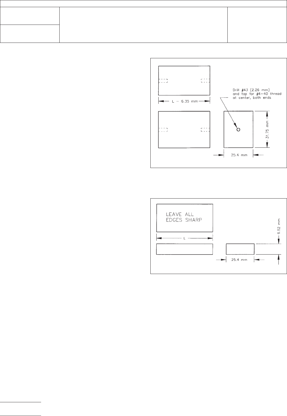
5.1.1
For
each L value, two ground tool steel clamping bars
25.4 mm x 28.58 mm x (L-6.35), as shown in Figure 3. These
are intended to provide uniformly distributed force along the
length of the specimen, transferred through part 5.1.2. A rec-
ommended practice is to provide these with a small diameter
threaded rod, such as #4-40, centered on each end and
extending about 20 mm to serve as a means for attaching the
probe assembly of 5.2 used in 6.1.5 or the alignment jig of
5.1.3 used in 6.1.1.
5.1.2
For
each L value, two pure copper ground plates 25.4
mm x 9.52 mm x L with all edges sharp as in Figure 4. These
provide at the ends a copper surface perpendicular to the
specimen length direction, which serves as a contact area
over a range of specimen thicknesses for making ground con-
tinuity to the coaxial probe. When these are clamped with
5.1.1 as described in 6.1.1, the inside corners at each end
between the outer face of 5.1.2 and the end surface of 5.1.1
form reference locations equidistant from the center line of the
stripline resonator element that are used by the probe assem-
bly 5.2 to align the coaxial probe with that center line.
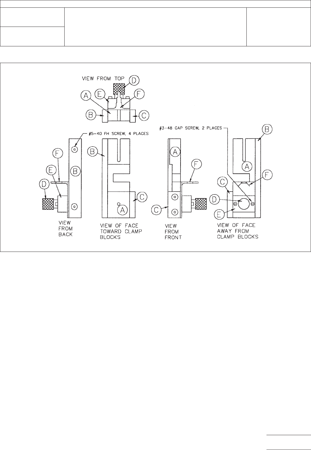
5.1.3
A
stacking alignment jig as used in 6.1.1 of an appro-
priate design. Figure 5 shows a suggested design.
5.1.4
A
low profile mechanical force gage with 4.45 kN
compression capacity such as a Dillon Model U, PN 30482-
0053, available from Dillon Quality Plus, Inc., 1140-T Avenida
Acaso, Camarillo, CA 993012. One is needed for each of part
5.1.5.
5.1.5
A
clamping arrangement with 5.1.4 properly mounted
in the line of force and with alignment parts for assuring the
line of force is properly located through the stack assembled
IPC-25551-3
Figure
3 Three View Drawing of a Steel Clamping Bar
(See 5.1.1) Cut to Length for the 50.8 mm L Value
(Extended #4-40 Threaded Rod Both Ends is Not Shown)
IPC-25551-4
Figure
4 Three View Drawing of a Copper Ground Plate
(See 5.1.2) for the 50.8 mm L Value
IPC-TM-650
Number
2.5.5.5.1
Subject
Stripline
Test for Complex Relative Permittivity of Circuit Board
Materials to 14 GHz
Date
3/98
Revision
P
age4of11
电子技术应用 www.ChinaAET.com
according
to 6.1.2. This can be a manually adjustable
mechanical screw fixture such as a vise, clamp, or a pneu-
matic cylinder fixture with a pressure regulator. One of com-
ponent 5.1.5 with 5.1.4 is needed for every 152 mm of speci-
men length L. See Figure 6.
5.2
Probe Assembly
Two
probe assemblies are needed;
one for each end of the clamped stack. They can be designed
to be attached to the ends of the clamp bars 5.1.1. The fol-
lowing items are needed for each assembly.
5.2.1
Semi
rigid coaxial cable 1.8 mm size about 230 mm
long with 3 mm connector and adapters to the electronic
instrumentation. The probe end of the cable has the center
conductor extending 1.8 mm.
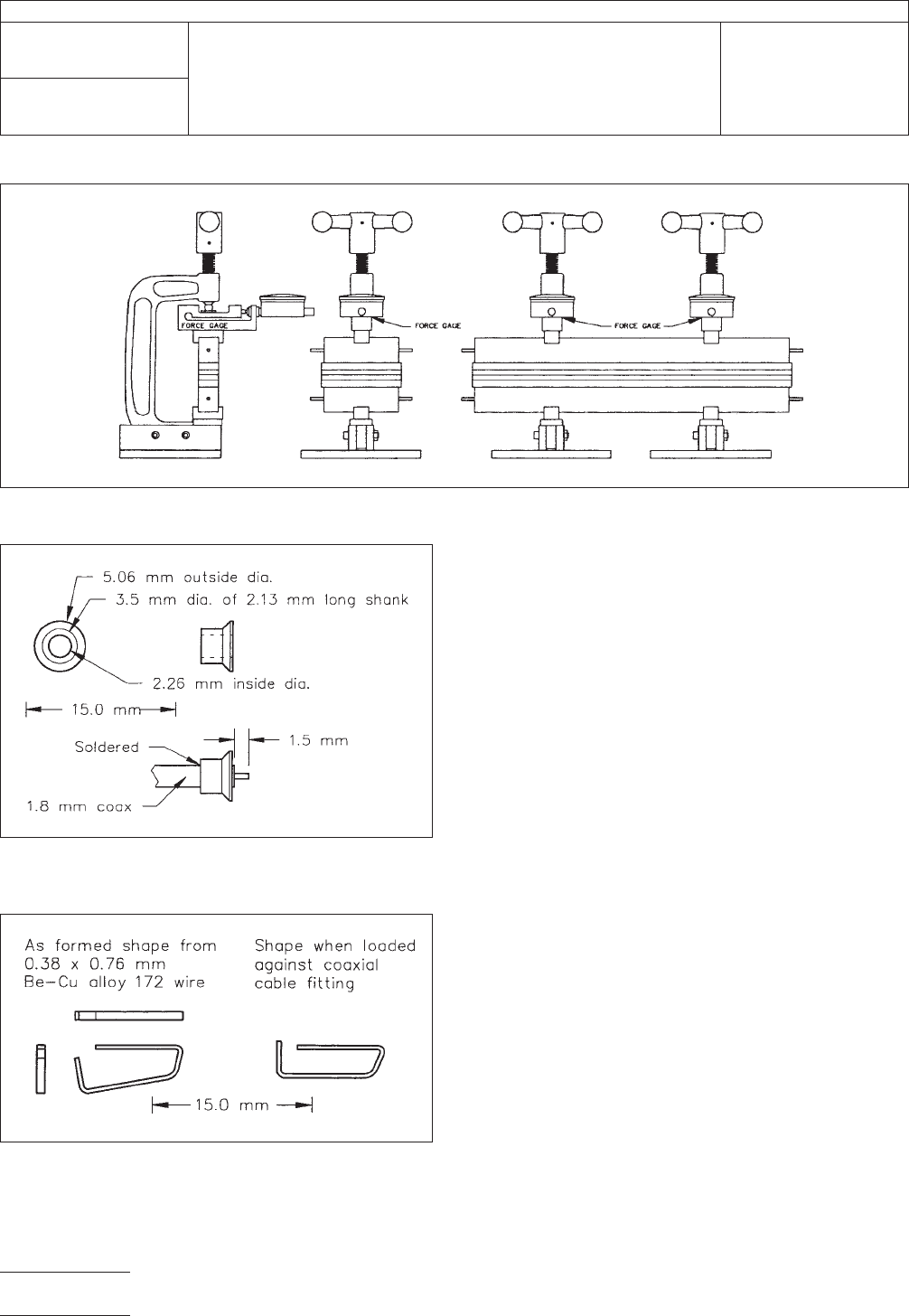
5.2.2 Copper
fitting with reversed bevel soldered to the end
of the coaxial cable jacket, as shown in Figure 7.
5.2.3
A
means for effecting ground contact between 5.2.2
and both of 5.1.2. Figure 8 shows a suggested beryllium-
copper alloy wire part. Two are required, as shown in the sec-
tional views of Figure 9.
5.2.4
Mechanical
assembly capable of attaching to the ends
of 5.1.1 and using the locations of the inside corners of 5.1.1
and 5.1.2 to align parts 5.2.1 through 5.2.3 with the center
line of the stripline resonator. It must accommodate various
specimen thicknesses, provide alignment of 5.2.1 through
5.2.3, make contact pressure of 5.2.3 to 5.1.2, provide con-
trolled adjustment of the gap between specimen end and
5.2.1, and provide support for the coaxial cable connector to
the instrumentation.
A wide variety of hardware designs for accomplishing the
alignment required in 6.1.5 are acceptable if the following con-
ditions are met for each of the two probes:
IPC-25551-5
Figure
5 Five Assembly Views for a Suggested Two Member Stacking Alignment Jig (See 5.1.3)
Note: Only the right-handed member is shown. Part A with 3.175 mm deep recessed area on the face towards the clamp blocks
assures 6.1.1 items b, c, and d. Its notched out area allows 6.1.1 item 5. Part B assures 6.1.1, item a. Part C eases mounting the jig
member to the end of the lower steel bar (see 5.1.1). Knurled #4-40 nut D, retained by E, fastens A against the steel bar with its
extended threaded rod. Part F assists in meeting 6.1.1, item e.
IPC-TM-650
Number
2.5.5.5.1
Subject
Stripline
Test for Complex Relative Permittivity of Circuit Board
Materials to 14 GHz
Date
3/98
Revision
P
age5of11
电子技术应用 www.ChinaAET.com
•
The center line of the coaxial cable end and the centerline of
the stripline resonator in the specimen are aligned within a
tolerance of 0.2 mm vertically and horizontally.
• Both parts 5.2.3 (Figure 8) are held aligned so they are cen-
tered in a vertical plane through the probe axis, each mak-
ing firm electrical contact to 5.2.2 (Figure 7) and to the end
edge surface of part 5.1.2 (Figure 4).
• The coaxial probe end longitudinal position is adjustable so
that the gap between it and the specimen center conductor
is controllable to a tolerance of ± 0.03 mm.
6.0
Measuring Procedure
6.1 Preparation for Testing
The
actual length of the
specimen and resonator element shall be determined by a
vernier caliper or other means capable of accuracy to ± 0.03
mm or smaller.
Unless otherwise specified, specimens shall be stored before
testing at 18°C to 24°C and 50% ± 5% relative humidity. The
referee minimum storage time is 16 hours. Shorter times may
be used if they can be shown to yield equivalent test results.
If electronic equipment as listed in 4.1 is used, it shall be
turned on at least one half hour before use to allow warm-up
and stabilization. The automatic frequency counter listed in
4.1 is provided with temperature control of the clock crystal
that operates even when the power switch is off. Care should
be taken to assure that power is continuously supplied to this
unit to avoid a longer warm-up time. Other equipment using
vacuum tube devices will require a longer warm-up time, as
specified in the manufacturer’s literature.
IPC-25551-6
Figure
6 Clamp Arrangement (See 5.1.5) Showing Side and Front Views for Specimen Lengths of 76.2 mm and 304.8 mm
IPC-25551-7
Figure
7 Copper Fitting with Reverse Bevel (See 5.2.2)
Soldered to the 1.8 mm Semi-Rigid Coaxial Cable Probe
IPC-25551-8
Figure
8 Formed Be-Cu Alloy Wire for Ground Continuity
from Coaxial Cable Fitting to Copper Ground Plate
IPC-TM-650
Number
2.5.5.5.1
Subject
Stripline
Test for Complex Relative Permittivity of Circuit Board
Materials to 14 GHz
Date
3/98
Revision
P
age6of11
电子技术应用 www.ChinaAET.com