IPC-TM-650 EN 2022 试验方法.pdf - 第713页
1 Scope This test method is used to determine the resis- tance of the applied solder mask to reverting to liquid when exposed to high humidity at a specific time and temperature condition. This test method evaluates the …

Parallax
displacement distortion will be indicated when round
holes appear oval or ‘‘cats eyed’’ on the X-ray image. For a
hole drilled through a panel of thickness, t, and offset from the
center of the X-ray beam axis by the angle A, the parallax dis-
placement between the top and bottom of the hole will be
equal to
txT
ran A.
5.2
Radiographic Quality Standard
A
radiographic qual-
ity standard such as an ASTM Image Quality Indicator or other
agreeable indicator shall be used on all radiographic studies.
5.3
Exposure when film is used
The
necessary X-ray
penetration exposure will depend on the construction of the
multilayer, X-ray source anode voltage, the anode current, the
distance from the source to the film plane and the speed or
sensitivity of the film. The exposure should be sufficient to
produce an optical density of at least 2.0 at those portions of
the film receiving the highest X-ray exposure, such as, holes
or unattenuated areas. In addition the conditions of paragraph
1.0 with respect to resolution and gray scale must be met.
The exposure apparatus for film can consist of an industrial
shielded X-ray cabinet with a nominal anode voltage of 80
kilovolts, nominal anode current of
3
millgrams
and
a focal
spot to film distance adequate to avoid parallax distortion of
the X-ray film image.
5.4
Exposure for realtime systems
The
X-ray source
operating parameters must be matched to the X-ray camera
sensitivity of the system to produce an X-ray image of suffi-
cient quality to comply with the conditions of paragraph 1.0.
6.0 Notes
None
IPC-TM-650
Number
2.6.10
Subject
X-Ray
(Radiography), Multilayer Printed Wiring Printed Board
Test Methods
Date
8/97
Revision
A
P
age2of2
电子技术应用 www.ChinaAET.com

1 Scope This test method is used to determine the resis-
tance of the applied solder mask to reverting to liquid when
exposed to high humidity at a specific time and temperature
condition. This test method evaluates the stability of a cured
solder mask that has been applied to a printed board under
storage (nonoperating) conditions.
2 Applicable Documents
IPC-SM-840
Qualification and Performance of Permanent
Solder Mask
3 Test Specimens Three copper clad laminates, approxi-
mately 10 cm x 10 cm [3.94 in x 3.94 in], coated with solder
mask and cured according to the supplier’s recommenda-
tions.
4 Equipment
4.1 Desiccator
At least 25 cm [9.84 in] in diameter
4.2 Potassium Sulfate Reagent grade potassium sulfate
4.3 Cotton Swabs
4.4 Oven
Capable of maintaining temperature up to 100 °C
[212 °F]
4.5 Test Chamber Capable of maintaining a constant tem-
perature of 97±2°C[206.6 ± 3.6 °F] with 94 ± 4% relative
humidity.
4.6 High Temperature Silicone Grease
5 Procedures
5.1 Desiccator Method
5.1.1
Prepare a saturated solution of distilled or deionized
water and potassium sulfate [35 grams per 100 mL] at a tem-
perature of 97±2°C[206.6 ± 3.6 °F]. Pour the solution into
the desiccator just below the ceramic plate. Crystals of potas-
sium sulfate should remain visible in the saturated solution
during testing.
Note: Relative humidity is not to exceed 98%.
5.1.2 Place the three test specimens on the ceramic plate in
the desiccator so that they are not touching each other.
5.1.3 Seal the desiccator with high temperature silicone
grease and close the desiccator.
5.1.4 Place the desiccator in the oven maintained at 97 ± 2
°C [206.6 ± 3.6 °F].
5.1.5 Allow the desiccator, containing the test specimens,
to remain in the oven for 28 days (672 hours).
5.2 Chamber Method
5.2.1
Place the three test specimens in a rack so they do
not touch each other and place the rack into the test cham-
ber. Close the chamber door.
5.2.2 Set the chamber’s parameters at 97±2°C[206.6 ±
3.6 °F] and 94 ± 4% relative humidity. Activate the test cham-
ber and begin testing.
5.2.3 Allow the specimens to remain in the test chamber for
28 days (672 hours).
5.3 Evaluation
5.3.1
After the required time exposure remove the test
specimens and visually examine the specimens for evidence
of reversion as indicated by softening, chalking, blisters,
cracks, tackiness, loss of adhesion or liquefaction.
5.3.2 Touch (do not wipe) the surface of the solder mask
coating with a swab of absorbent cotton and observe for par-
ticles of the cotton adhering to the coating.
Note: Examination and testing may be done at intervals
within the required exposure time, if there is suspicion of early
failure and evaluation time is critical.
3000 Lakeside Drive, Suite 309S
Bannockburn, IL 60015-1249
IPC-TM-650
TEST METHODS MANUAL
Number
2.6.11
Subject
Solder Mask - Hydrolytic Stability
Date
03/07
Revision
D
Originating Task Group
Solder Mask Performance Task Group (5-33b)
Material in this Test Methods Manual was voluntarily established by Technical Committees of IPC. This material is advisory only
and its use or adaptation is entirely voluntary. IPC disclaims all liability of any kind as to the use, application, or adaptation of this
material. Users are also wholly responsible for protecting themselves against all claims or liabilities for patent infringement.
Equipment referenced is for the convenience of the user and does not imply endorsement by IPC.
Page1of1
ASSOCIATION CONNECTING
ELECTRONICS INDUSTRIES
®
1
Scope
This
test method is to determine the resistance of
the applied conformal coating to reverting to liquid when
exposed to high humidity at a specific temperature and time
condition for each class. This test method is to evaluate the
quality of the coated printed boards under storage conditions
(nonoperating).
2
Applicable Documents
IPC-CC-830
Qualification
and Performance of Electrical Insu-
lating Compound for Printed Board Assemblies
FED-STD-141
Method
4061 (Dry-Through For Varnish, Lac-
quers And Enamels)
3
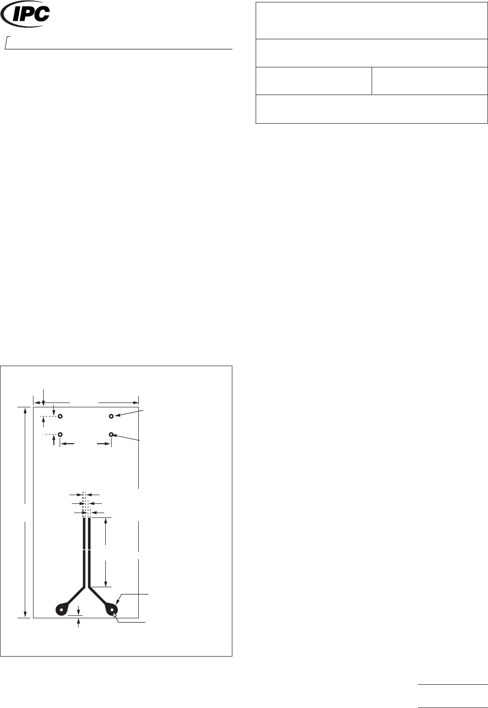
Test Specimens
Five
coated ‘‘Y’’ shape patterns (see
Figure 1) containing two resistors, one with marking ink and
one with color code bars, coated with conformal coating per
the coating supplier’s recommendations.
4
Equipment
4.1 Desiccator
At
least 25 cm [9.84 in] in diameter
4.2
Potassium Sulfate
Reagent
grade potassium sulfate
4.3
Cotton Swabs
4.4 Oven
Capable
of maintaining temperature up to 100°C
[212°F].
4.5
Test Chamber
Capable
of maintaining a constant tem-
perature of 85° ± 2°C [185° ± 3.6°F] with 95 ± 4% relative
humidity
4.6
Soldering Iron
If
applicable
4.7
High Temperature Silicone Grease
5.0 Procedures
5.1 Desiccator Method
5.1.1
Prepare
a saturated solution of distilled or deionized
water and potassium sulfate (35 grams per 100 cm
3
)a
ta
temperature of 85° ± 2°C [185° ± 3.6°F]. Pour the solution
into the desiccator just below the ceramic plate. Crystals of
potassium sulfate should remain visible in the saturated solu-
tion during testing.
Note: Relative humidity is not to exceed 98%.
5.1.2 Place
four of the five test specimens on the ceramic
plate in the desiccator so that they are not touching each
other. The fifth specimen is used as a control.
5.1.3
Seal
the desiccator with high temperature silicone
grease and close the desiccator.
5.1.4
Place
the desiccator in the oven maintained at 85° ±
2°C [185° ± 3.6°F].
5.1.5 Allow
the desiccator, containing the test specimens,
to remain in the oven for 120 days.
75 mm
[2.95 in]
4.7 mm
[0.185 in]
38 mm
[1.50 in]
19 mm
[0.748 in]
6.30 mm [0.248 in]
2.3 ± 0.13 mm DIA
[0.091 ± 0.005 in DIA]
Hole 0.75 ± 0.08 mm DIA
[0.029 ± 0.003 in DIA]
0.75 mm [0.029 in MIN]
0.75 mm ± 008 mm [0.029 in ± 0.003 in MIN]
0.75 mm [0.029 in MIN]
3.2 mm
[0.126 in]
25 ± 1.5 mm
[0.984 ± 0.059 in MIN]
3.8 ± 0.13 mm DIA
[0.150 ± 0.005 in DIA]
HOLE 1.3 ± 0.08 mm DIA
[0.051 ± 0.0031 in DIA]
IPC-26111-1
Figure
1 ‘‘Y’’ Shape Pattern
2215
Sanders Road
Northbrook, IL 60062-6135
IPC-TM-650
TEST
METHODS MANUAL
Number
2.6.11.1
(Supersedes
2.6.11B for Conformal Coating Test)
Subject
Hydrolytic Stability - Conformal Coating
Date
07/00
Revision
Originating Task Group
Conformal Coating Task Group (5-33a)
Material
in this Test Methods Manual was voluntarily established by Technical Committees of IPC. This material is advisory only
and its use or adaptation is entirely voluntary. IPC disclaims all liability of any kind as to the use, application, or adaptation of this
material. Users are also wholly responsible for protecting themselves against all claims or liabilities for patent infringement.
Equipment referenced is for the convenience of the user and does not imply endorsement by IPC.
P
age1of2
ASSOCIA
TION CONNECTING
ELECTRONICS INDUSTRIES
电子技术应用 www.ChinaAET.com