IPC-TM-650 EN 2022 试验方法.pdf - 第167页
6.0 Notes 6.1 Preventative Maintenance, Troubleshooting 6.1.1 Depending upon the bath chemistry as analyzed, con- dition of the panel relative to uniformity, burning, cloud pat- terns skip plate, etc., modification by co…
5.1.3
Cold
water rinse.
5.1.4
Wipe
surface with Hull Cell sponge that has been
soaked in D.I. water.
5.1.5
Observe
panel for water break free condition. Repeat
5.1.4 and 5.1.5 as necessary.
5.1.6
For
plastic coated brass panels-remove plastic film by
peeling it off.
5.1.7
Soak
in mild soak cleaner.
5.1.8 Reserve
current clean at 2 amps for one minute.
5.1.9
Cold
water rinse.
5.1.10
Acid
dip 10% C.P. Hydrochloric Acid for 5 seconds.
5.1.11
Cold
water rinse.
5.1.12
Observe
for water break free surface; repeat steps
5.1.7 through 5.2.11 if necessary.
5.2
Test
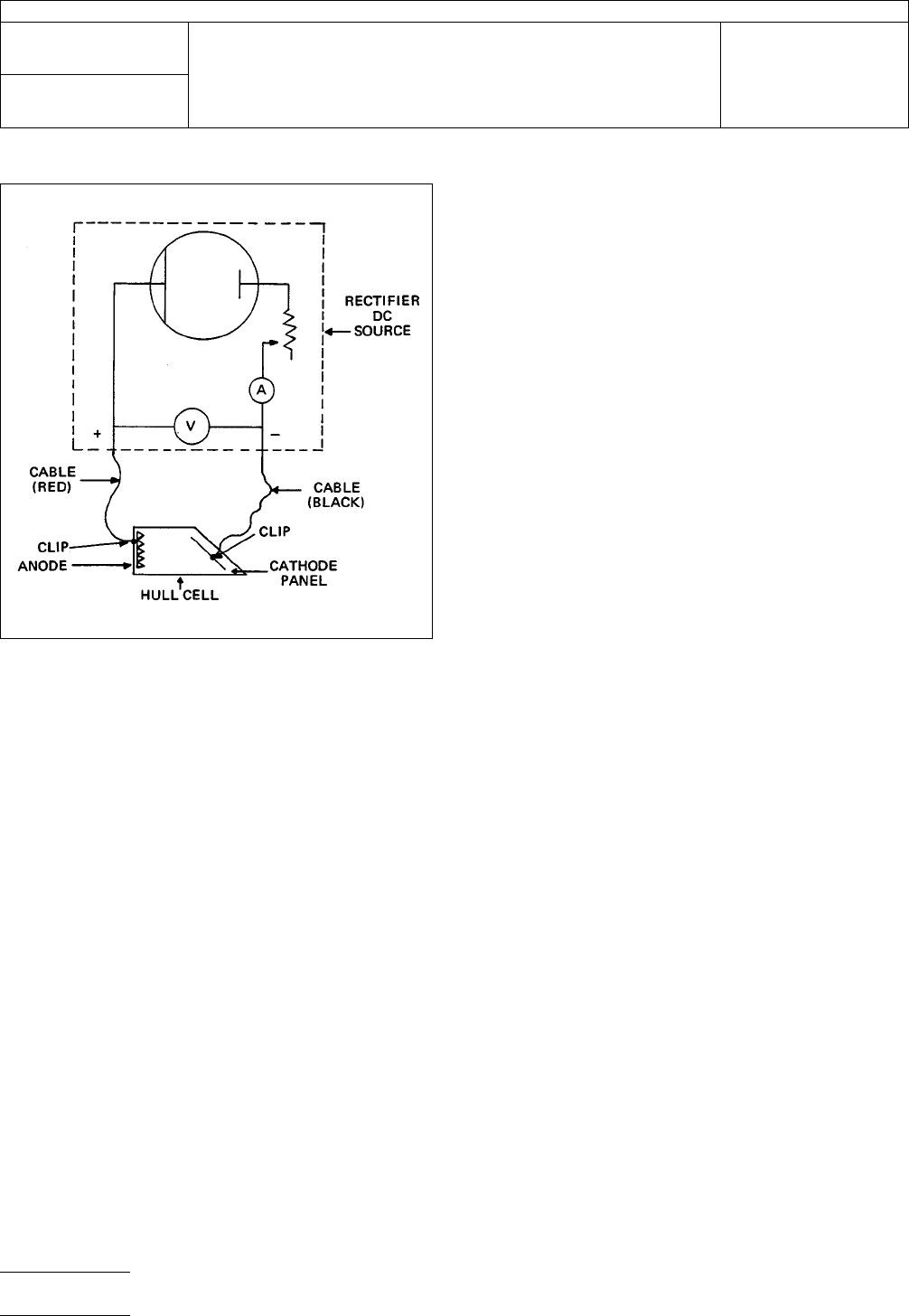
Insert
cathode test panel along the slanted side of
the Hull Cell (it just fits), which has solution to scribed line.
5.2.1
Hook
red cable to anode (+).
5.2.2
Hook
black cable to cathode (–).
5.2.3
Set
timer to prescribed time (see tech bulletin).
5.2.4
Turn
on power source.
5.2.5
Adjust
power to described amperage.
5.2.6
Start
time.
5.2.7 At
prescribed time, shut off power.
5.2.8
Disconnect
cathode cable.
5.2.9
Remove
cathode panel.
5.2.10
Cold
water rinse.
5.2.11
Complete
desired post plate treatment if any-
example: dipping panel in 1/4 to 1/2 of 1% by volume. Nitric
Acid (C.P. Grade) for 3-5 seconds enhances the ability to
interpret the panel on zinc and cadmium plating solutions.
5.2.12
Warm
Water Rinse.
5.2.13
Dry, forced air or even wiping with a water absorbent
paper towel.
5.2.14
An
alternate method of drying the panels is to water
rinse followed by an alcohol rinse to drive off the water. Also,
a method of preserving samples is to spray them immediately
with a clear lacquer to prevent oxidation.
5.3
Evaluation
5.3.1
See
Bulletin ‘‘The Hull Cell’’ or proprietors data sheets
utilizing the Hull Cell Scale appropriate for the amperage used
as the guide to current densities.
5.3.2 Hull
Scale use: place the bottom edge of the ‘‘as
plated’’ on the line that matches the amperage plating was
performed. The areas on the panel above these numbers are
the area of that number’s current density.
IPC-2321-1
Figure
1 Hull Cell Hook Up
IPC-TM-650
Number
2.3.21
Subject
Plating
Quality Hull Cell Method
Date
8/97
Revision
A
P
age2of3
电子技术应用 www.ChinaAET.com

6.0 Notes
6.1
Preventative Maintenance, Troubleshooting
6.1.1
Depending
upon the bath chemistry as analyzed, con-
dition of the panel relative to uniformity, burning, cloud pat-
terns skip plate, etc., modification by controlled additions can
be made to the Hull Cell plating solution and procedures can
be repeated. Changes caused by addition to the Hull Cell will
duplicate results to be expected by the same proportionate
additions to the main plating bath.
6.1.2 Correlations
of thickness checks in the controlled
time, temperature, amperage cathode panel will also tell the
optimum plating range to obtain plating thickness desired.
6.1.3
Source of applicable documents:
R.O.
Hull and Co., Inc.
3203 W. 71st
Cleveland, OH 44102
IPC-TM-650
Number
2.3.21
Subject
Plating
Quality Hull Cell Method
Date
8/97
Revision
A
P
age3of3
电子技术应用 www.ChinaAET.com

1
Scope
This
test method is used to determine the pres-
ence and effectiveness of the protective coating deposited
over the PWB to prevent oxidation and facilitate good wetting
during soldering operations. The coating is removed during
soldering.
2
Applicable Documents
None
3
Test Specimens
3.1
Any
pre-production or production copper clad board at
least 5 cm x 5 cm. The specimen must either contain circuitry
or be completely copper clad. An uncoated bare copper clad
specimen must also be available for control purposes.
4
Equipment/Apparatus
4.1
Reagent
or commercial grade ferric chloride (42BE’)
etchant
4.2
Petrie
dishes or glass trays
4.3
Stop
watch
4.4
Lint-free
cloth
5 Procedure
5.1 Test
5.1.1
Place
one drop of ferric chloride on several locations
on the test specimens and the bare copper control speci-
mens.
5.1.2
Allow
to stand 10 seconds, then rinse with tap water
and wipe dry.
5.2
Evaluation
5.2.1
Examine
specimens and compare with bare control
specimen. Test specimens must show no copper etching,
proving the presence and effectiveness of protective coating.
6
Note
Slight
‘‘mottling’’ or a slight attack on the coated
surface indicates uneven deposition or insufficient solids of the
coating.
The
Institute for Interconnecting and Packaging Electronic Circuits
2215 Sanders Road • Northbrook, IL 60062-6135
IPC-TM-650
TEST
METHODS MANUAL
Number
2.3.22
Subject
Copper
Protective Coating Quality
Date
2/78
Revision
Originating Task Group
N/A
Material
in this Test Methods Manual was voluntarily established by Technical Committees of the IPC. This material is advisory only
and its use or adaptation is entirely voluntary. IPC disclaims all liability of any kind as to the use, application, or adaptation of this
material. Users are also wholly responsible for protecting themselves against all claims or liabilities for patent infringement.
Equipment referenced is for the convenience of the user and does not imply endorsement by the IPC.
P
age1of1
电子技术应用 www.ChinaAET.com