IPC-TM-650 EN 2022 试验方法.pdf - 第251页
1 Scope This method is designed to determine the peel strength of metal foil when bonded to thin laminates. Peel strength is determined for specimens as received or after con- ditioning, such as solder immersion or eleva…
5.2.3.7
Rinse
in hot water at 55 ± 5°C [131 ± 9°F] for5±1
minutes.
5.2.3.8
Dry
for 30 ± 5 minutes at 125 ± 5°C [257 ± 9°F].
5.2.3.9
Immerse
in a hot oil bath maintained at 220 ± 5°C
[428 ± 9°F] for 40 ± 5 seconds.
5.2.3.10
Immerse
in degreaser as specified in 4.4.4 at 23 ±
2°C [73.4 ± 3.6°F] for 75 ± 5 seconds to remove hot oil.
5.2.3.11
Air
dry specimens and perform steps 5.2.1.2
through 5.2.1.7.
5.2.4
Determination of Degradation
Examine
the speci-
mens using normal or corrected 20/20 vision. Record and
report the presence of any base laminate degradation, includ-
ing loss of surface resin, discoloration, resin softening, delami-
nation, blistering, propagation of imperfections, measling,
crazing, or voids.
5.3
Calculation and Report
5.3.1
Calculate
the peel strength as per the formula:
lbs/in =
L
M
W
S
where:
L
M
=
Minimum Load
W
S
=
Measured width of peel strip
5.3.2
Record
and report each individual peel strength value.
Average the individual peel strength values for each side and
each grain direction of the laminate sampling. For example, if
the sampling plan calls for one specimen per side and per
grain direction, there will be at least two values to be averaged
from four different specimens.
5.3.3
Report
any presence of laminate degradation as
observed in 5.2.4
6.0 Notes
6.1
Test
strip breakage may be caused by either a bond
greater than the tensile strength of the foil, or foil brittleness.
Where superior bond is shown (value at break above specifi-
cation) the value at break may be used instead of minimum
peel. The average reported shall indicate that the value is
greater than average.
6.2 For
metallic cladding less than one oz thickness, copper
plating or solder coating may be used to build up to 0.035 ±
0.0035 mm [0.0014 ± 0.00014 in] to provide strip strength.
6.3
Environmental
aspects of chemicals as specified in 4.4.1
and 4.4.4. Based on industry and government policies toward
chemicals which are hazardous to worker health or of concern
for ozone depletion, previous requirements for use of Methyl-
ene Chloride and 1,1,1 Trichloroethane have been replaced
with equivalents.
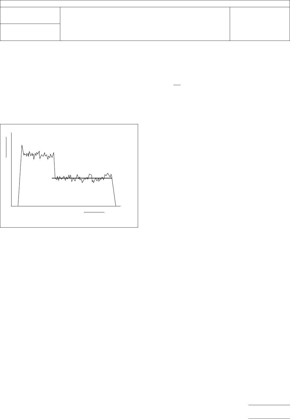
IPC-I-002102
Figure
1 Multiple Failure Modes
Peel Distance
▼
▼
Load
High Peel Strength
Failure Mode
Low Peel Strength
Failure Mode
Minimum
Average
Load
IPC-TM-650
Number
2.4.8
Subject
Peel
Strength of Metallic Clad Laminates
Date
12/94
Revision
C
P
age3of3
电子技术应用 www.ChinaAET.com
1
Scope
This
method is designed to determine the peel
strength of metal foil when bonded to thin laminates. Peel
strength is determined for specimens as received or after con-
ditioning, such as solder immersion or elevated temperature
exposure.
2
Applicable Documents
IPC-TM-650
Test
Methods Manual
2.4.8 Peel Strength of Metallic Clad Laminates
3
Test Specimen
Bonded
metal foil with peel strength test
patterns 3 mm wide and up to 76 mm long (each specimen is
about 60 mm to 76 mm long)
4
Apparatus
4.1
Force
gage or testing machine capable of a travel speed
of 5 cm per minute with a range of 1 kg to 1.4 kg and 4.5 g
minimum scale divisions
4.2
Keyhole
test plate per Figure 1, or equivalent
4.3
Keyhole
horizontal base fixture per Figure 2
4.4
Chain
61 cm to 71 cm
4.5 Surgical
hemostat
4.6
Cylindrical
spring paper clips (Boston clip No. 4, Hunt
Mfg. Co.)
4.7
Chain
to hemostat adapter, per Figure 3 (approximately
76 mm long)
4.8
Scalpel
5
Procedure
5.1 Preparation
5.1.1
Cut
specimens from a laminated or bonded and
etched panel and trim to the edge of the peel tabs.
5.1.2
Make
a cut about 6.35 mm to 9.5 mm along each side
of the peel tab, bend up the peel tab 90°, break the laminate,
and pull up without breaking the foil.
5.1.3
Pull
up the foil about 3 mm to 6.35 mm for about a 9.5
mm to 13 mm starting length (a scalpel can be used to start
the foil peel).
5.2
Conditioning
If
specimens are to be conditioned ,the
conditions in IPC-TM-650, Method 2.4.8, shall be used. Other
conditions of specifications working this method as applicable
may be used.
5.3
Test
5.3.1
Place
the specimen on the base fixture, metal foil side
up, and center the peel strip on the base.
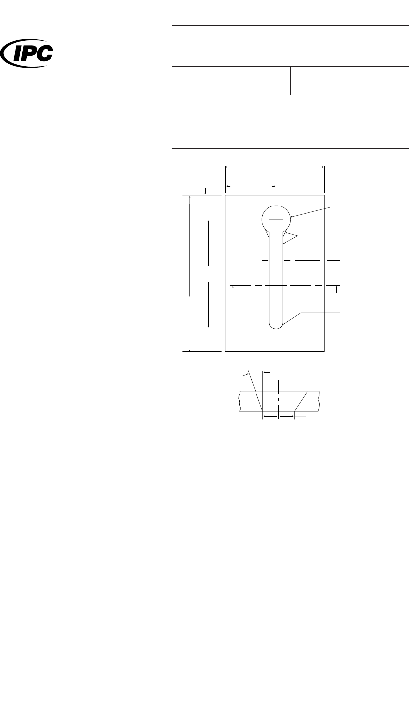
IPC-2-4-8-1-1
Figure
1 Keyhole Test Plate
8.5 cm
± 0.13 cm
‘‘A”
‘‘A”
3.8 cm ± 0.25 cm
2 cm
± 0.25 cm
13.5 cm
± 0.25 cm
8 cm ± 0.25 cm
1.9 cm
Blend entry edge of
hole into bevel of slot
0.4 cm ± 0.013 cm (Slot)
R
0.3 cm thick
AL Alloy
AA6061 T651
Pl
18 ± 2
0.41 cm Ref.
Section “A”-“A” Bevel detail 4x
+ 0.02 cm
- 0.013 cm
dia. hole
o
o
The
Institute for Interconnecting and Packaging Electronic Circuits
2215 Sanders Road • Northbrook, IL 60062-6135
IPC-TM-650
TEST
METHODS MANUAL
Number
2.4.8.1
Subject
Peel
Strength, Metal Foil (Keyhole Method For Thin
Laminates)
Date
1/86
Revision
Originating Task Group
N/A
Material
in this Test Methods Manual was voluntarily established by Technical Committees of the IPC. This material is advisory only
and its use or adaptation is entirely voluntary. IPC disclaims all liability of any kind as to the use, application, or adaptation of this
material. Users are also wholly responsible for protecting themselves against all claims or liabilities for patent infringement.
Equipment referenced is for the convenience of the user and does not imply endorsement by the IPC.
P
age1of3
电子技术应用 www.ChinaAET.com
5.3.2
Place
the keyhole plate over the peel strip with the tab
in the large hole and the strip centered in the slot.
5.3.3
Clamp
the keyhole plate to the base with the paper-
clips, making sure the alignment is not disturbed.
5.3.4
Attach
the hemostat to the tab so the peel will be 90°
to the strip (the hemostat should be attached to the chain with
the adapter and hanging from the tester jaws or force gage so
that the tab can be clamped without excessive bending or
damage).
5.3.5
Start
the vertical pull (5 cm per minute) with the test
head and initiate a chart recorder or visually observe the mini-
mum and pull force.
5.3.6
Lower
the head or force gage to position for starting
the next peel strip and repeat starting at 5.2.1.
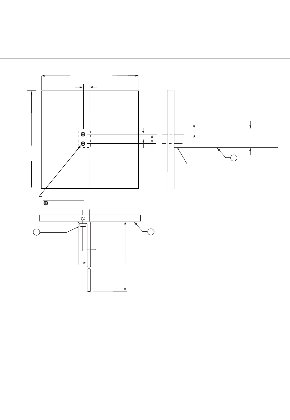
IPC-2-4-8-1-2
Figure
2 Keyhold Horizontal Axis
10 cm ±
0.25 cm
(2) .138-32UN-2B
0.025 cm dia.
0.064 cm
± 0.05 cm
10 cm ± 0.25 cm
0.475 cm
± 0.025 cm
0.95 cm ±
0.025 cm
2
0.064 cm
AL Allo
y
0.475 cm
± 0.05 cm
0.95 cm ± 0.075 cm
3
MS 16995
SCR CAP SOC HD
10.5 cm
± 0.075 cm
AA6061 T651
0.475 cm
± 0.025 cm
1.9 cm
± 0.025 cm
0.4 cm
+ 0.013 cm
- 0.0075 cm
dia.
2 holes
0.32 cm thic
k
AL Alloy
AA6061 T651
1
GI
IPC-TM-650
Number
2.4.8.1
Subject
Peel
Strength, Metal Foil (Keyhole Method For Thin Laminates)
Date
1/86
Revision
P
age2of3
电子技术应用 www.ChinaAET.com