IPC-TM-650 EN 2022 试验方法.pdf - 第707页
1.0 Scope The purpose of this test method is to provide a consistent procedure to test the sensitivity of electronic com- ponents to ultrasonic energy. There has been reluctance in the electronics industry to use ultraso…
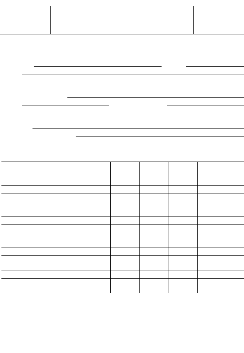
Ultrasonic
Test Data Record
Name
of tester
Date
Company
Address
Phone Fax
Make
and model of equipment
T
ank size
Dimensions
(cm cm x cm)
Generator
output power
Frequency
(KHz)
No.
of boards tested per trial
Substrate
Exposure
time
Other
stress testing (pre- or post-)
Describe
Component
tested No. tested Passed Failed Comments
Type Mfgr Part #
Mail
to: IPC Fax to: 847-509-9798
2215 Sanders Road
Northbrook, IL 60062-6135
Attn: Ultrasonic Cleaning Task Group
IPC-TM-650
Number
2.6.9.1
Subject
Test
to Determine Sensitivity of Electronic Assemblies to
Ultrasonic Energy
Date
1/95
Revision
P
age5of5
电子技术应用 www.ChinaAET.com

1.0
Scope
The
purpose of this test method is to provide a
consistent procedure to test the sensitivity of electronic com-
ponents to ultrasonic energy. There has been reluctance in
the electronics industry to use ultrasonic energy for printed
board assembly cleaning because of the possibility of damage
to wire bonds in active, hermetically sealed components or
other damage that might cause latent failures.
Recent work has shown that electronic components have a
low potential for damage from ultrasonics (References 1-7)
under conditions seen in most cleaning processes. In addi-
tion, MIL-STD-2000 Rev. A and J-STD-001 now allow for the
use of ultrasonic cleaning, as does the proposal for IEC TC91
International Standards based on an updated revision of the
J-STD-001.
1.1
Definitions
Ultrasound:
All
sound in frequencies above the range of
human hearing. For the purpose of ultrasonic cleaning, fre-
quencies between 18-800 KHz are in commercial use. In the
lower frequency ranges, fluid cavitation is the primary agitation
method. In the higher frequency ranges, microstreaming
(i.e., fluid pumping) is believed to be the form of mechanical
agitation.
Frequency:
The
number of periodic oscillations, vibrations of
waves per unit of time, usually expressed in cycles per second
(Hertz).
Generator:
An
electronic system which converts the 50 or 60
Hz power line electricity into an ultrasonic frequency drive sig-
nal which powers the transducers in their resonant frequency
range.
T
ransducers:
Convert
electrical energy from the generator into
mechanical (vibratory) energy, producing high intensity sound
waves in a liquid and causing cavitation of microstreaming.
Transducers are primarily of two types, piezoelectric and mag-
netostrictive.
Piezoelectric:
Piezoelectric
ceramics, which change dimen-
sions in the presence of an electric field. Thickness varies in
response to an applied voltage. Conversion efficiency =
70-90%.
Magnetostrictive:
Made
of nickel or its alloys, it changes length
when placed in a magnetic field. Conversion efficiency =
20-50%.
Cavitation:
The
rapid formation and oscillation or violent col-
lapse of microscopic bubbles or cavities in a liquid, produced
by introducing high frequency (ultrasonic) sound waves into a
liquid. The agitation from countless implosions of these
bubbles create a highly effective scrubbing of both exposed
and hidden surfaces of parts immersed in the cleaning solu-
tion.
Degas:
The
act of removing entrained gas from cleaning fluid.
Gas bubbles tend to absorb ultrasonic energy, thereby
decreasing the amount of energy available for cleaning.
Power
Density:
Average
output power of ultrasonic generator
divided by total volume of liquid being sonified.
2.0
Applicable Documents
2.1 Institute for Interconnecting and Packaging Elec-
tronic Circuits (IPC)
IPC-T-50
Terms
and Definitions for Interconnecting and
Packaging Electronic Assemblies
IPC-CH-65
Guidelines
for Cleaning of Printed Boards and
Assemblies.
2.2
Joint Industry Standards
J-STD-001
Requirements
for Soldered Electrical and Elec-
tronic Assemblies
2.3
Military
MIL-STD-2000 Rev. A
Standard
Requirements for Soldered
Electrical and Electronic Assemblies
2.4
Other Publications
IEC-TC-91
Proposed
International Standard (based on
J-STD-001) International Requirements for Soldered Electrical
and Electronic Assemblies using Surface Mount and Related
Assembly Technologies.
3.0
Test Specimens
The
components to be tested should
be the exact type and package style the tester intends to use
in production. A statistically valid number of each type and
package style of interest should be tested.
4.0
Apparatus
The
Institute for Interconnecting and Packaging Electronic Circuits
2215 Sanders Road • Northbrook, IL 60062-6135
IPC-TM-650
TEST
METHODS MANUAL
Number
2.6.9.2
Subject
Test
to Determine Sensitivity of Electronic
Components to Ultrasonic Energy
Date
1/95
Revision
Originating Task Group
Ultrasonic Cleaning Task Group (5-31e)
Material
in this Test Methods Manual was voluntarily established by Technical Committees of the IPC. This material is advisory only
and its use or adaptation is entirely voluntary. IPC disclaims all liability of any kind as to the use, application, or adaptation of this
material. Users are also wholly responsible for protecting themselves against all claims or liabilities for patent infringement.
Equipment referenced is for the convenience of the user and does not imply endorsement by the IPC.
P
age1of4
电子技术应用 www.ChinaAET.com
4.1
Tank
Testing
shall be done in an ultrasonic tank, pref-
erably in the equipment to be used in production. Water is to
be used as the ultrasonic transmission testing fluid, regardless
of the cleaning agent to be used in the production process.
Water will degas, transmit ultrasonics, and cavitate more eas-
ily than most new cleaning agents and is, therefore, consid-
ered a ‘‘worst case’’ ultrasonic testing fluid. Care must be
taken to maintain water level during testing. Water tempera-
tures should be maintained at 60°C ±5°C (140°F ± 10°F).
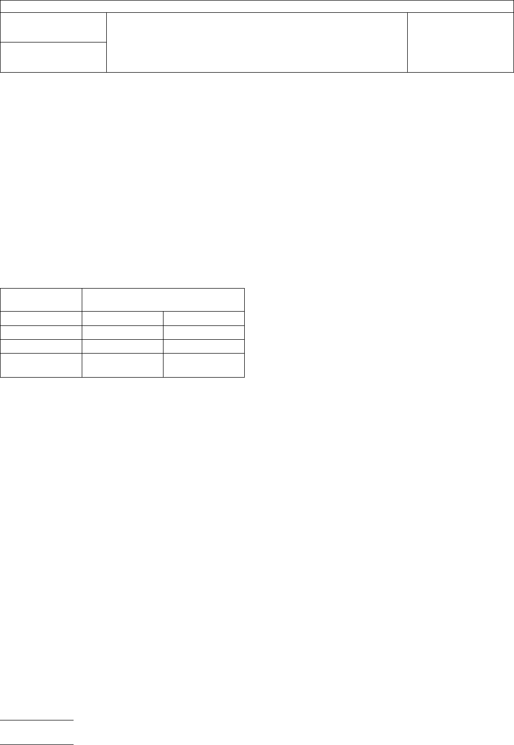
It is recommended that testing equipment operate near 40Khz
or higher and have a power output in the range listed in the
chart below. Power is measured as the output from the gen-
erator to the transducers. Note in the chart that the amount of
power necessary is scaled for various tank sizes.
T
ank Size
liters (gallons)
Power Density
watts/liter (watts/gallon)
Magnetostrictive Piezoelectric
19
(5) 66-76 (250-290) 33-38 (125-145)
38 (10) 53-68 (200-220) 26.5-29 (100-110)
95 and greater
(25 and greater)
21-32 (80-120) 10.5-16 (40-60)
If frequencies other than 40 KHz range or power densities or fre-
quencies differing from the ranges listed above are to be used in
production, they should be used in testing as well, and noted on
the Ultrasonic Test Data Record.
4.2 Basket
Loose
components will be placed randomly in
a basket or in a beaker (pyrex or stainless steel) for testing. If
a basket is used, it should be made of stainless steel and
preferably have a solid bottom for optimal ultrasonic transmis-
sion. Tight mesh should always be avoided. If a beaker is
chosen, plastic is not acceptable as it will dampen ultrasonic
transmission.
5.1
Procedure
Note:
Standard ESD handling methods should be used in
handling and assembly so as not to have ESD damage misin-
terpreted as damage by ultrasonic exposure.
5.1.1
Perform
functional electrical tests on components to
be subjected to ultrasonic energy. All components should go
though standard prescreening tests to eliminate infant mortal-
ity. Note any anomalies and ignore any malfunctions in further
testing.
5.1.2 Fill
the test tank with de-ionized water. Turn on ultra-
sonics and allow a minimum of 15 minutes for the water to
degas. Evidence of cavitation should be obtained by placing a
piece of aluminum foil in the water for one minute and inspect-
ing for an erosion pattern (evidence of cavitational activity). If
the surface of the foil is not disrupted, continue to degas until
the foil confirms ultrasonic activity.
Test components in the equipment described above. Place
components randomly in basket or in a beaker. Baskets
should be suspended off the bottom of the tank or contain
stand off legs to keep it from setting directly on the bottom of
the tank. If a beaker is to be used, it should be filled with
deionized water and degassed as described in the above
paragraph. The beaker should be suspended in the water-
filled tank and not placed on the tank bottom.
Subject specimens to ultrasonics for a time period 10 times
longer than the expected exposure anticipated under normal
cleaning conditions or thirty minutes, whichever is longer.
5.1.3
(Optional)
Conduct
any environmental stressing
test(s) as specified by the reliability requirement of the product
line in concern.
5.2
Evaluation Method
5.2.1
Repeat
the functional electrical test in 5.1.1. Any fail-
ures should be analyzed for cause of failure. Any failure,
excluding those noted in 5.1.1 or attributable to a docu-
mented defect will also be considered caused by the ultrason-
ics.
5.2.2
Any
defect which is not assignable to a previously
documented defect will also be considered caused by ultra-
sonics.
5.2.3
Any
component exhibiting no failures or 100% reliabil-
ity after ultrasonic testing will be considered safely resistant to
ultrasonics under the conditions tested. Any component with
less than 100% reliability will be suspect unless subsequent
testing can demonstrate that it is 100% reliable. Unless clas-
sified or proprietary, please report test results to the Ultrasonic
Energy Task Group through the IPC for compilation in the
attached list.
It is important that the IPC receives as much data as
possible, whether it be to support previously submitted
data, add new data, or provide conflicting data for cer-
tain components. All information received will be
entered into a database for all IPC members to access.
The data will prove more useful as the volume of data
increases.
IPC-TM-650
Number
2.6.9.2
Subject
Test
to Determine Sensitivity of Electronic Components to
Ultrasonic Energy
Date
1/95
Revision
P
age2of4
电子技术应用 www.ChinaAET.com