IPC-TM-650 EN 2022 试验方法.pdf - 第285页
1.0 Scope To determine the tensile strength (in PSI) and the elongation (in percentage) of copper foil at ambient and elevated temperatures by mechanical force testing. 2.0 Applicable Documents ASTM-E-345 Tensile Strengt…
7 Calculations
7.1 Low Extensible Films
For base dielectric films that
have load-time charts characterized by Figure 2, the average
tear propagation force in grams [ounces] is obtained by aver-
aging the load indicated on the chart over the time period,
disregarding the initial and final portions of the curve. Record
the average load value reading from the tensile testing
machine. The average resistance to tearing shall be calcu-
lated from all specimens tested in each of the transverse and
longitudinal directions.
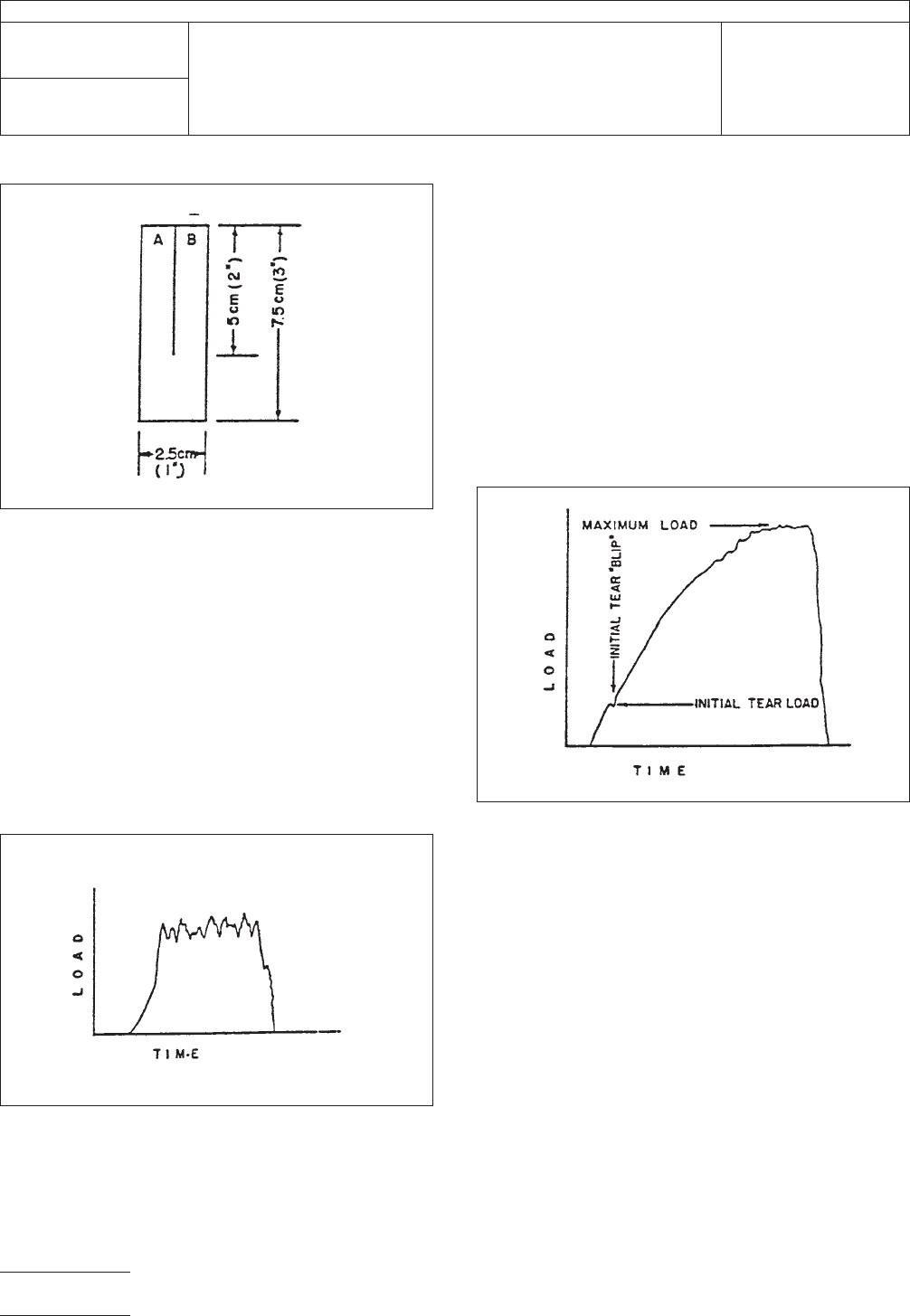
7.2 High Extensible Films For base dielectric films that
have load-time charts characterized by Figure 3, the initial
force to continue the propagation of the slit and the maximum
force attained are obtained from the chart and reported in
grams [ounces]. The initial force may be more readily detected
by placing a dot approximately 3 mm [1/8 in] in diameter at
the base of the razor blade slit with a wax pencil. As the load
is applied to the sample, the dot area is observed. When the
load is just sufficient to begin the extension of the slit, a ‘‘blip’’
is introduced on the chart (see Figure 3) by pushing the
appropriate button on the recorder or the equivalent to mark
this point. The maximum load is the highest reading on the
chart as indicated. Calculate the average of the five initial tear-
propagation forces and the average of the five maximum tear-
propagation forces in grams [ounces] for the transverse and
longitudinal directions of the material test specimens.
8 Report
8.1
Report the average base dielectric film thickness only of
the specimens tested. This provides the user of this test
method with the base dielectric film thickness only, if required,
by the flexible circuitry material specifications.
8.2 For low extensible base dielectric films described in 7.1,
report the average of the five average tear propagation deter-
minations in grams [ounces] for the transverse and longitudi-
nal specimens.
8.3 For high extensible base dielectric films described in 7.2,
report the average of the five initial tear-propagation forces
and the average of the five maximum tear-propagation forces
in grams [ounces] for the transverse and longitudinal
specimens.
IPC-24171-1
Figure 1 Single-tear specimens
IPC-24171-2
Figure 2 Load-time chart for low-extensible base
dielectric films
IPC-24171-3
Figure 3 Load-time chart for high extensible base
dielectric films
IPC-TM-650
Number
2.4.17.1
Subject
Propagation Tear Strength, Flexible Insulating Material
Date
1/13
Revision
B
Page2of2

1.0
Scope
To
determine the tensile strength (in PSI) and
the elongation (in percentage) of copper foil at ambient and
elevated temperatures by mechanical force testing.
2.0
Applicable Documents
ASTM-E-345
Tensile
Strength
3.0
Test Specimens
Copper
foil sufficient in size to permit
cutting or etching of five specimens 10 inches x
1
⁄
2
inch.
Specimens
must be clean cut and free of burrs and nicks.
4.0
Apparatus
4.1
Constant
strain rate tensile tester capable of pulling at
rate of 0.050 and 2.0 inches/minute.
4.2
JDC
#50 sample cutter
1
⁄
2
inch
wide x 10 inches long.
4.3
A
shear to cut 10 inches long sample to 6 inches long.
4.4
Mettler
Balance type P120 or equivalent.
4.5
Elevated
temperature chamber or fixture, attachable to
the tensile tester, capable of reaching and maintaining a tem-
perature of 180°C ±10°C during sample testing.
5.0
Procedure
5.1 Preparation of Samples
5.1.1
The
sample should be smooth and undistorted
(wrinkle free).
5.1.2
Use
the JDC #50 to cut five tensile specimens.
5.1.3
Cut
the five 10 inches long specimens to 6 inches
long.
Note: Accuracy is important in the
1
⁄
2
inch
x 6 inches dimen-
sions because it is used to determine foil thickness and cross-
sectional area.
5.2
Weighing Samples
5.2.1
Weigh
tensile sample to at least three places beyond
the decimal point, in grams.
5.2.2
Record
the weight and calculate the mean average
cross-sectional area.
Note: The density of electrodeposited copper is 8.909 gm/cc
(16.389 cc/in
3
x
8.909 gm/cc = 146 gm/in
3
).
The
density of rolled copper is 8.93 gm/cc (16.389 cc/in
3
x
8.93
gm/cc = 146.35 gm/in
3
).
Mean
average thickness =
Weight
of tensile sample in grams
Area of Tensile
sample in sq.
inches
X
The density
of copper in
gm/in
3
Mean
avg. cross-sectional area =
Weight
of tensile sample in grams
Area of Tensile
sample in sq.
inches
X
The density
of copper in
gm/in
3
5.3
General Test Information
5.3.1
If
the tensile tester is equipped with an area compen-
sator, dial the mean average cross-sectional area into it. If not
then the cross-sectional area has to be used to compute the
tensile strength.
Note:
Tensile Strength
in
lbs/in
2
=
Load
used to break sample in lbs.
Mean
average cross−sectional area
If Tensile Tester is equipped with area compensator after the
test is complete, the Tensile Strength can be read directly
from the chart.
5.3.2
Ambient Temperature Testing
5.3.2.1
Select
load range.
5.3.2.2
Place
the sample in the jaws of the Tensile Tester
The
Institute for Interconnecting and Packaging Electronic Circuits
2215 Sanders Road • Northbrook, IL 60062-6135
IPC-TM-650
TEST
METHODS MANUAL
Number
2.4.18
Subject
Tensile
Strength and Elongation, Copper Foil
Date
8/80
Revision
B
Originating Task Group
Printed Board Test Methods (7-11d)
Material
in this Test Methods Manual was voluntarily established by Technical Committees of the IPC. This material is advisory only
and its use or adaptation is entirely voluntary. IPC disclaims all liability of any kind as to the use, application, or adaptation of this
material. Users are also wholly responsible for protecting themselves against all claims or liabilities for patent infringement.
Equipment referenced is for the convenience of the user and does not imply endorsement by the IPC.
P
age1of2
电子技术应用 www.ChinaAET.com

being
careful that it is properly centered and the axis aligned
with the jaws.
5.3.2.3
Test Conditions
(1) Gage length 2.0 inches
(2) Crosshead speed 2.0 inches/min.
(3) Chart speed 20 inches/min.
Note: At a chart speed of 20 inches/min., a gage length of
2.0 inches and a crosshead speed of 2.0 inches/min. each
one inch of chart paper equals 5.0% linear elongation.
5.3.3
Elevated Temperature Testing
5.3.3.1
Select
load range.
5.3.3.2
Bring
temperature chamber or fixture up to 180°C
±10°C.
5.3.3.3
Open
temperature chamber and clamp foil sample
between tensile jaws. (Note: Caution must be exercised to
avoid excessive clamping pressures and to provide good
sample alignment for testing.)
5.3.3.4
Close
temperature chamber and monitor sample
temperature with a thermocouple. Permit foil sample to dwell
at 180°C temperature for 5 minutes prior to tensile test. Maxi-
mum time at temperature should not exceed 10 minutes.
5.3.3.5
Test Conditions
(1)
Gage length 2.0 inches
(2) Crosshead speed 0.050 inches/min.
(3) Chart speed 20 inches/min.
Note: At a chart speed of 20 inches/min., a gage length of
2.0 inches and a crosshead speed of 0.050 inches/min., each
one inch of chart paper equals 0.125% linear elongation.
Note: Temperature chamber contains normal ambient air.
Inert gas atmosphere is not necessary, but may be used.
5.4
Evaluation
5.4.1
Activate
crosshead to break sample and make calcu-
lations of tensile strength in pounds/in
2
and
elongation in %.
5.4.2
Percent
elongation may be determined by fitting the
ends of the fractured specimen together carefully and mea-
suring the distance between the original gage marks to the
nearest 0.01 inch. Elongation is the increase in length of the
gage length, expressed as a percentage of the original gage
length.
Percent elongation =
length at break −original gage length X 100
original
gage length
5.4.3
Average
all five elongation readings.
6.0 Notes
6.1
For
guidance, typical values for tensile strength and
elongation are:
TENSILE
STRENGTH
Oz/ft
2
Electrodeposited
Standard
or high ductility As rolled
Light cold
rolled Annealed
lb/in
2
lb/in
2
lb/in
2
lb/in
2
1/2
15,000 50,000 — 15,000
1 30,000 50,000 — 25,000
2 & over 30,000 50,000 25,000 25,000
ELONGATION
Oz/ft
2
Electrodeposited
As
rolled
Light cold
rolled AnnealedStandard High ductility
percent
percent min. percent min. percent min. percent
1/2 2 5 1/2 — 5
1 3 10 1/2 — 10
23151520
IPC-TM-650
Number
2.4.18
Subject
Tensile
Strength and Elongation, Copper Foil
Date
8/80
Revision
B
P
age2of2
电子技术应用 www.ChinaAET.com