IPC-TM-650 EN 2022 试验方法.pdf - 第111页
F-Operation • A filter for removing surface shapes (i.e., Plane tilt, curved surface). • Insures that the geometry of the sample surface does not affect the magnitude of the measured roughness value. • Eliminates the use…
APPENDIX A
A.1 Surface Roughness Standard: ISO 25178-2 This
ISO standard is grouped into six different categories and each
of these values are reported in the ‘‘Height Parameters’’ sec-
tion. The conventional ISO 4287:2001 was defined for
contact-type tools and does not provide as much detail as the
ISO 25178-2 standard.
A.1.1 Filter Type: Gaussian Filter This is used for deter-
mining the mean plane in surface metrology. This is defined by
ISO 1661 and is applied to areal surface roughness measure-
ments.
A.1.2 Surface Type: S-L Surface Defines a surface
obtained after using the L-Filter. This filter removes undula-
tions and other surface variations, allowing for the measure-
ment of only the surface topography/texture without
geometric influence.
A.1.3 S-Filter This is chosen based on the specifications of
the objective lens used to capture the data. This filter elimi-
nates the smallest scale elements from the surface, shortest
wavelength filter. S-filter should be no smaller than the spot
size multiplied by 2.5.
A.1.4 F-Operation: Plane Correction Chosen based on
the planar features of the surface of metallic foils.
A.1.5 L-Filter This is chosen based on the area of the total
minimum scanned section (1000 µm X 200 µm). This filter
eliminates the largest scale elements from the surface, longest
wavelength filter. L-filter should be no larger than entire scan
length divided by 5.
A.2 Filter Selection and Filter Explanations
A.2.1
The main differentiator between the ISO 4287 and ISO
25178 is how the acquired data set is processed to maximize
the accuracy of the calculated roughness values. The old
standard used terms like λs and λc to account for the stylus
tip size and total evaluation length, which are specific towards
contact profilers. The newest standard uses filters to account
for similar features of noncontact 3-D profilers: the objective
lens used for analysis and total XYZ coverage area. Listed
below is additional detail to describe how the S-filter,
F-operation and L-filter are defined.
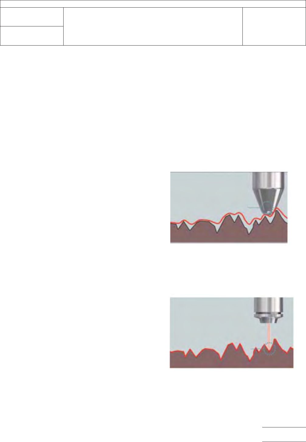
S-Filter:
• Commonly known as a low-pass filter.
• This filter is equivalent to λs for line roughness defined by
ISO 4287.
• Eliminates noisy data that varies based on the size of beam
spot. This will vary based on the objective lens chosen for
the analysis. (see below for explanation)
Low mag lens, larger beam spot, high
S-filter value
High mag lens, smaller beam spot, low
S-filter value
Vs.
IPC-TM-650
Number
2.2.22
Subject
Noncontact Metallic Foil Surface Topography/Texture
Date
5/20
Revision
Page3of5
F-Operation
• A filter for removing surface shapes (i.e., Plane tilt, curved
surface).
• Insures that the geometry of the sample surface does not
affect the magnitude of the measured roughness value.
• Eliminates the user from having to place the sample per-
fectly flat during the scan.
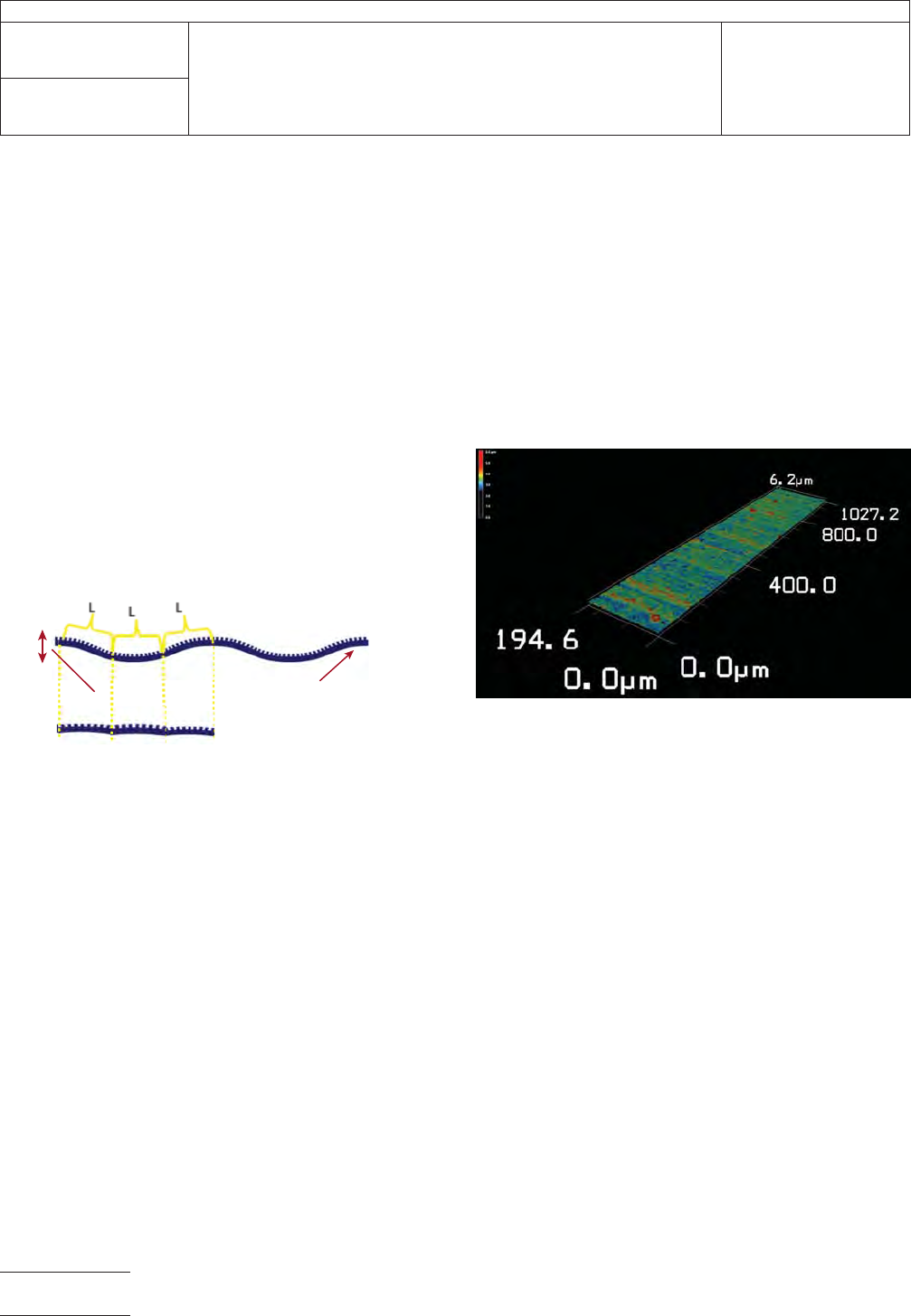
L-Filter
• Commonly known as a high-pass filter.
• This filter is equivalent to λc for line roughness defined by
ISO 4287.
• Removes waviness and other nonuniform surface shapes to
extract surface roughness data (normalization filter).
A.2.2 As described in Section V, the proper filter values that
properly align with the ISO 25178 for this specific procedure
(50X objective with 0.95 NA, 200 µm X 1000 µm scanned
area) are:
• S-filter: 2 µm
• F-operation: Plane Correction
• L-filter: 0.2 mm
A.3 Sample Measurements Examples
A.3.1
Shown below are examples of what the user should
expect from a successful analysis with a 3-D measurement
tool. The first picture shows a qualitative 3-D rendering of the
metallic foil surface from a laser confocal microscope tool.
A.3.2 A laser confocal microscope, or similar noncontact
3-D surface measurement tool should be able to provide
enough resolution in both the XY and Z direction to provide an
accurate representation of the material.
A.3.3 Once the 3-D model is obtained, the surface will then
be quantified using the ISO 25178 Surface Roughness mod-
ule.
A.3.4 An example of how the data could be outputted is
shown below. Other similar forms of data outputs would be
provided to the user by other noncontact 3-D measurement
tools.
Surface roughness
Surface waviness
IPC-TM-650
Number
2.2.22
Subject
Noncontact Metallic Foil Surface Topography/Texture
Date
5/20
Revision
Page4of5
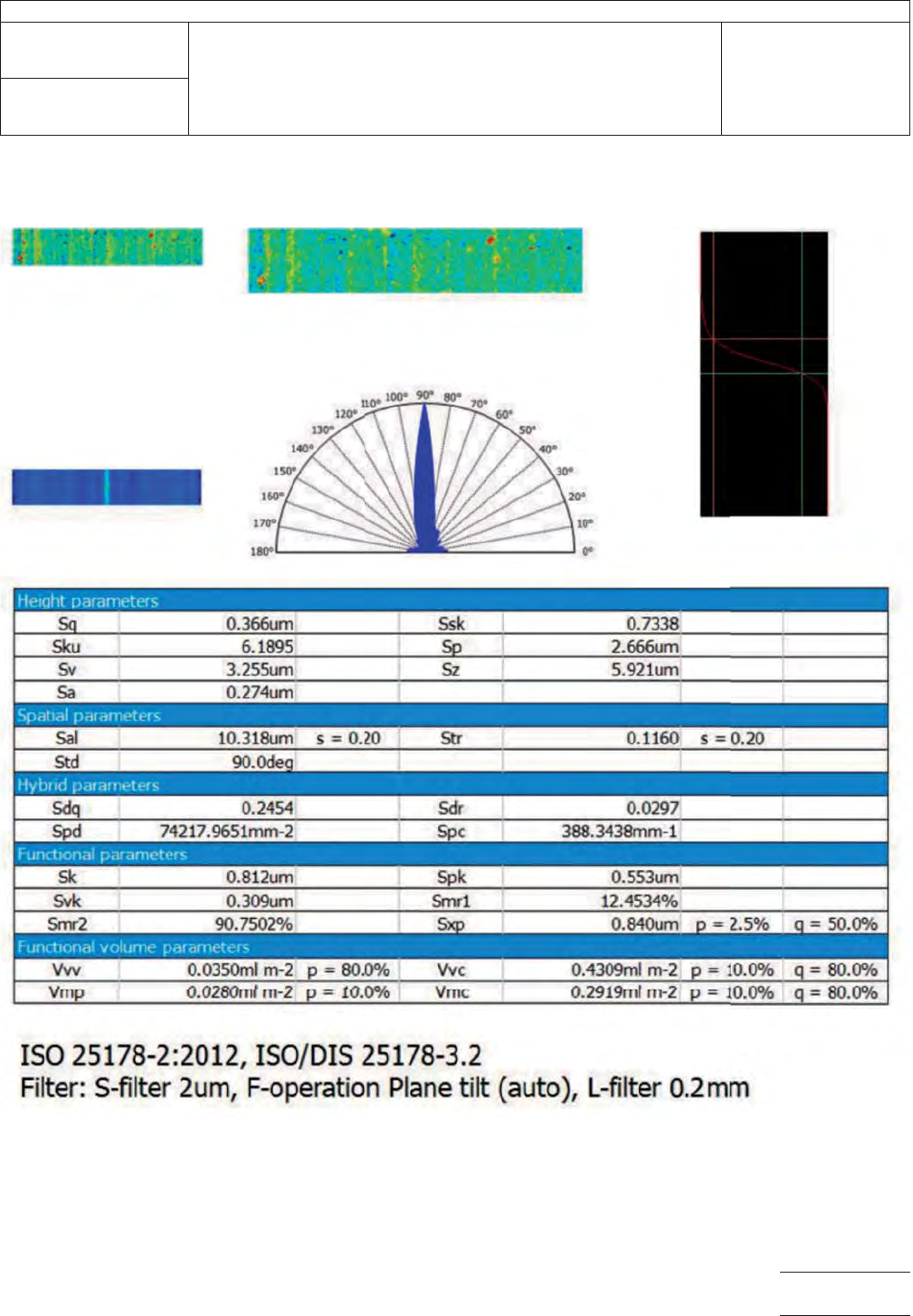
Main image (Height) S-L surface Material ratio curve
Angular spectrum
Autocorrelation function
2.66um
IPC-TM-650
Number
2.2.22
Subject
Noncontact Metallic Foil Surface Topography/Texture
Date
5/20
Revision
Page5of5