IPC-TM-650 EN 2022 试验方法.pdf - 第784页
1.0 Scope 1.1 To determine the effect on the connector of prolonged exposure to conditions of high humidity at various tempera- tures. Two conditions of test are provided as follows: Steady State Test Used to evaluate th…
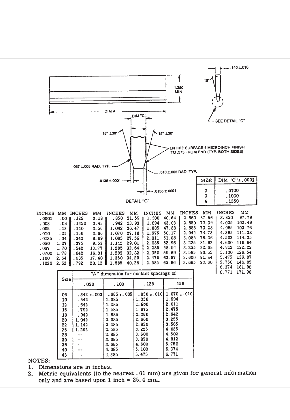
Figure 1 One Piece Edge Connector Mechanical Gages
IPC-TM-650
Number
3.4
Subject
Durability, Connectors
Date
1/83
Revision
B
Page2of2

1.0 Scope
1.1
To determine the effect on the connector of prolonged
exposure to conditions of high humidity at various tempera-
tures. Two conditions of test are provided as follows:
Steady State Test
Used to evaluate the hydroscopic nature
of insulating materials as evidenced by deteriorated physical
properties (dimensions, mechanical strength, etc.) or
degraded electrical properties (e.g., insulation resistance).
Humidity—Temperature Cycling Test
Used to evaluate the
effectiveness of seals and gaskets in the presence of a pres-
sure differential induced by varying temperatures; the corro-
sion resistance of metals and finishes exposed to alternate
periods of condensation and drying; and the hydroscopic
nature of insulating materials, with any degradation acceler-
ated by the ‘‘breathing’’ action imposed by varying tempera-
tures. Optional exposures to sub-freezing temperatures and
to mechanical vibration exaggerate any structural deterioration
of insulating materials.
2.0 Reference Documents
2.1
Information in this section is intended to parallel the test
method described in EIA-RS-364/TP-31.
3.0 Test Specimen
3.1
A connector (plug and receptacle) complete with appli-
cable guide, keying, and engaging hardware or a card- edge
receptacle and mating printed circuit board (if required by the
individual connector specification). The connector or recep-
tacle shall be mated or unmated as specified in the individual
connector specification.
3.2 Neither the plug nor the receptacle shall be mounted or
terminated during the test, unless such mounting (or termina-
tion) is necessary (1) to insure the mechanical integrity of the
component, (2) to measure the specified electrical character-
istic(s), (3) was a requirement of previously imposed environ-
mental or functional tests.
3.3 Printed circuit boards may be conformal coated to
reduce the effect of their deterioration due to moisture on the
connector characteristic(s) under evaluation. The coating shall
not be applied to any portion of the connector under test.
3.4 The plug, receptacle or mated connector shall be sus-
pended or supported within the test chamber in a normal (or
typical mounting attitude using non-corrosive material (e.g.,
plastic, corrosion resisting steel, etc.)). The technique utilized
shall not impede the flow of circulating air over and around the
test specimen.
4.0 Apparatus
4.1
A temperature-humidity chamber capable of maintaining
dry bulb temperatures from + 25°C to + 65°C within ± 2°C of
the set temperatures and relative humidity greater than 90%
during ascending or constant temperature operation and
greater than 80% during descending temperature operation.
Circulation of air within the chamber shall be at a minimum
cubic rate equivalent to five times of non-corrosive material
and shall prevent the dripping of condensate onto the test
specimen.
4.2 A temperature chamber, when required, capable of
maintaining a temperature of -10°C +0, -4°C.
4.3 A temperature measuring device, when required, of suit-
able range for the specified test condition.
4.4 A vibration system, when required, capable of producing
approximately simple harmonic motion at a double amplitude
of 0.60 inch in the frequency range from 10 to 55 Hz.
5.0 Procedure
5.1 Pre-Conditioning
The test specimen shall be condi-
tioned in a dry oven at a temperature of 50°C ±5°C for a mini-
mum period of twenty-four hours. After stabilization at room
ambient conditions, the test specimen shall be subjected to
the pre-test measurements specified in the individual connec-
tor specification.
5.2 Steady-State Test
5.2.1
The test specimen shall be suspended within the
humidity chamber and subjected to a relative humidity of
90-95% at a temperature of 40°C ± 2°C for a period of time
corresponding to one of the test conditions shown in Table 1.
Unless otherwise specified, Test Condition D shall apply.
2215 Sanders Road
Northbrook, IL 60062-6135
IPC-TM-650
TEST METHODS MANUAL
Number
3.5
Subject
Humidity, Connectors
Date
7/75
Revision
A
Originating Task Group
N/A
Material in this Test Methods Manual was voluntarily established by Technical Committees of the IPC. This material is advisory only
and its use or adaptation is entirely voluntary. IPC disclaims all liability of any kind as to the use, application, or adaptation of this
material. Users are also wholly responsible for protecting themselves against all claims or liabilities for patent infringement.
Equipment referenced is for the convenience of the user and does not imply endorsement by the IPC.
Page1of3
ASSOCIATION CONNECTING
ELECTRONICS INDUSTRIES
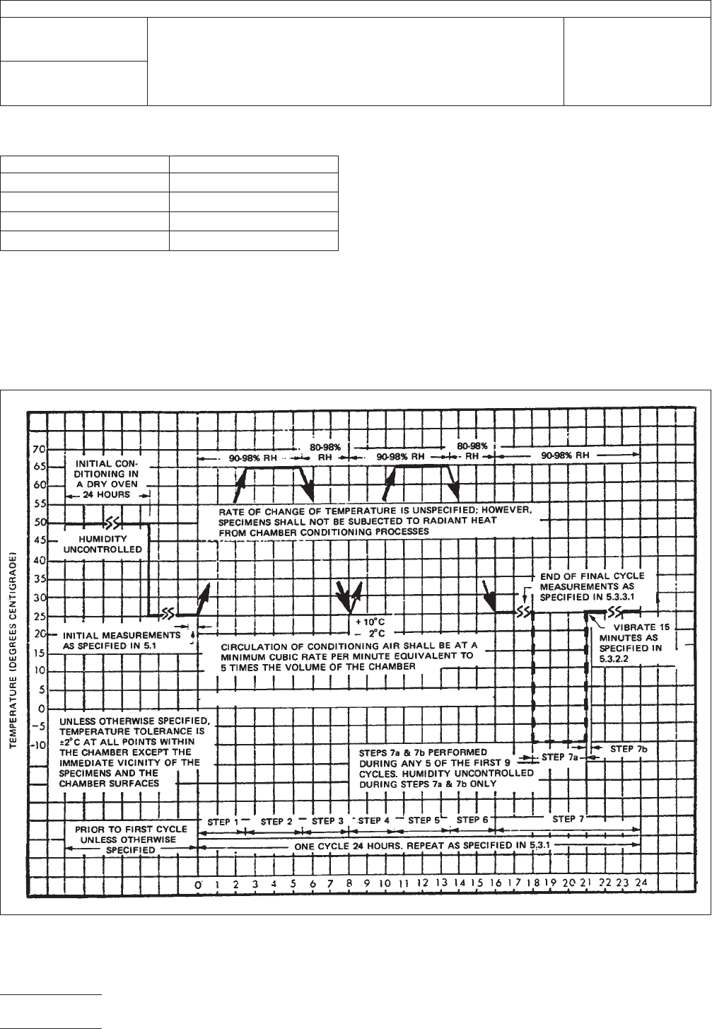
Table I Test Duration
Condition Length of Test (Days)
A56
B21
C10
D4
5.2.2 Final Measurements
5.2.2.1 At High Humidity (See 6.2)
Upon completion of
the exposure period, and while test specimen is still in the
chamber, the measurements specified in the individual con-
nector specification shall be performed.
5.2.2.2 During Recovery Period After removal from the
test chamber, and while maintained at room ambient condi-
tions, the test specimen shall be subjected to the specified
measurements during the specified recovery period.
5.2.2.3 After Recovery Period After being maintained at
room ambient conditions for five hours (or as otherwise speci-
fied) the required measurements shall be performed.
5.3 Humidity-Temperature Cycling Test
5.3.1
The test specimen shall be suspended within the
humidity chamber and subjected to the humidity-temperature
IPC-3-5-1
Figure 1 Graphical Representation of Moisture-Resistance Test
IPC-TM-650
Number
3.5
Subject
Humidity, Connectors
Date
7/75
Revision
A
Page2of3