IPC-TM-650 EN 2022 试验方法.pdf - 第660页
4.2 Power Supply Capable of producing a standing bias potential of 100 VDC with a tolerance of ± 10%. 4.3 Resistance Meter Capable of reading high resistance (10 12 ohms or greater), with a test voltage of 100 VDC. 4.4 O…
1 Scope This test method is used to determine the mois-
ture and insulation resistances of applied polymer solder mask
under two separate prescribed conditions of temperature and
humidity. One condition is described as Class T and the other
Class H. Raw material qualification testing is performed on
designated comb patterns. Production quality conformance
testing is performed on a standard ‘‘Y’’ pattern.
2 Applicable Documents
IPC-A-25A-G-KIT
1
Multipurpose One-Sided Test Pattern -
Gerber Format
IPC-SM-840 Qualification and Performance of Permanent
Solder Mask
J-STD-004 Requirements for Soldering Fluxes
IPC-A-600 Acceptability for Printed Boards
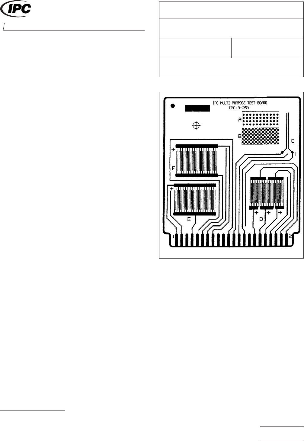
3 Test Specimens The IPC-A-25A-G-KIT artwork package
provides the Gerber files necessary for the fabrication of the
standard IPC-B-25A test board used with this test method.
3.1 Qualification Testing
3.1.1 Class H
Three IPC-B-25A boards using the D comb
patterns with 0.32 mm [0.0126 in] lines/spaces (see Figure 1).
Of which, two are to be coated and one uncoated with solder
mask according to the solder mask supplier’s recommenda-
tions.
3.1.2 Class T Three IPC-B-25A boards using the E and F
comb patterns with 0.41 mm [0.016 in] lines and 0.51 mm
[0.020 in] spaces (see Figure 1). Of which, two are to be
coated and one uncoated with solder mask according to the
solder mask supplier’s recommendations.
3.2 Conformance Testing IPC-B-25A board C (‘‘Y’’
shape) pattern with 0.64 mm lines/0.64 mm spacing [0.025 in
lines/0.025 in spacing] or pattern with minimum spacing on
the production board (see Figure 1), whichever has the small-
est line spacing, coated with solder mask according to the
solder mask suppliers recommendations.
4 Apparatus
4.1 Chamber
A clean chamber capable of programming
and recording an environment of 25±2°C[77±3.6°F]toat
least 65±2°C[149 ± 3.6 °F] and 90-98% relative humidity.
NOTE: This test requires a clean chamber and clean water
for repeatable test results. The following recommendations
are made:
• Incoming water purity should be between 0.5 and 0.1
micro-siemens/cm.
• Fresh deionized water should be used for each test, rather
than using a recirculating water sump.
• Chamber workspaces should be cleaned at least every six
months.
1. www.ipc.org/onlinestore
IPC-2631-1
Figure 1 IPC-B-25A Test Board
3000 Lakeside Drive, Suite 309S
Bannockburn, IL 60015-1249
IPC-TM-650
TEST METHODS MANUAL
Number
2.6.3.1
Subject
Solder Mask - Moisture and Insulation Resistance
Date
03/07
Revision
E
Originating Task Group
Solder Mask Performance Task Group (5-33b)
Material in this Test Methods Manual was voluntarily established by Technical Committees of IPC. This material is advisory only
and its use or adaptation is entirely voluntary. IPC disclaims all liability of any kind as to the use, application, or adaptation of this
material. Users are also wholly responsible for protecting themselves against all claims or liabilities for patent infringement.
Equipment referenced is for the convenience of the user and does not imply endorsement by IPC.
Page1of5
ASSOCIATION CONNECTING
ELECTRONICS INDUSTRIES
®

4.2 Power Supply Capable of producing a standing bias
potential of 100 VDC with a tolerance of ± 10%.
4.3 Resistance Meter Capable of reading high resistance
(10
12
ohms or greater), with a test voltage of 100 VDC.
4.4 Oven Capable of maintaining at least 120 °C [248 °F].
4.5 Timer
4.6 Solder Pot
4.7 Tongs
4.8 Soldering Iron
4.9 Flux
Water white rosin (R or RMA) with halide content
less than 0.5%, i.e., type Symbol A and B or ROL0 and ROL1
according to J-STD-004.
5 Test
5.1 Ambient Conditions
Class T and Class H: 25 +2/-5
°C [77 +3.6/-9 °F] and 40 - 50% relative humidity.
5.2 Test Conditions
5.2.1 Class T
65±2°C[149 ± 3.6 °F], with 90 ± 3% rela-
tive humidity, no bias, static, 24 hours.
5.2.2 Class H 25to65±2°C[77to149±3.6°F], with 90
+3/-5% relative humidity, 50 VDC bias, 20 cycles (160 hours
or 6
2
/3 days).
5.3 Specimen Preparation (Both Classes)
5.3.1
Positive, permanent and noncontaminating identifica-
tion of the test specimens is of paramount importance.
5.3.2 Visually inspect the test specimens for any obvious
defects, as described in IPC-A-600. If there is any doubt
about the overall quality of any test specimen, the test speci-
men shall be discarded.
5.3.3 One uncoated specimen subjected to the same pro-
cessing (except solder mask coating) as the coated speci-
mens shall be supplied with each set of coated samples for
testing as a control.
5.3.4 Subject one solder mask coated IPC-B-25A board to
solder in accordance with J-STD-004. Clean any residual flux
residue from the board surface using the following procedure:
1) Rinse with deionized or distilled water (30 seconds
minimum).
2) Immerse the board in 2-propanol and agitate (30 seconds
maximum). Gently scrub the board using a soft bristled
brush while submersed.
3) Spray the board with clean 2-propanol.
4) Bake in an oven at 50 °C [122 °F] for three hours minimum.
5.4 Electrical Connections (Both Classes)
5.4.1
For qualification purposes, single stranded PTFE
coated wire or some equivalent should be used to attach the
appropriate test pads (designated in 3.1) to the power supply
used for biasing and/or insulation resistance testing. When
soldering the wires onto the pads care should be taken to
ensure that the flux does not splatter onto the combs. A
simple noncontact shield fixture should be used to protect the
test patterns from flux splattering during soldering.
Note: An alternate method is to use gold plated alligator
clips.
5.4.2 For quality conformance purposes, single stranded
PTFE coated wire or an equivalent should be used to attach
the appropriate test pads of pattern C to the power supply for
insulation resistance testing.
5.5 Soldering Flux The flux shall not be removed.
Note: If the flux has contaminated the pattern on the control,
the sample shall be discarded and a new one used. It cannot
be cleaned because it will not represent the cleaning process
that was used prior to solder mask application.
5.6 Specimen Handling For the remainder of the test, the
surface of the test specimens either uncoated or coated with
solder mask shall not be handled or exposed to any other
contaminating influence. Handle all test specimens by the
edges only.
5.7 Class H Procedures
5.7.1 Class H Testing
IPC-TM-650
Number
2.6.3.1
Subject
Solder Mask - Moisture and Insulation Resistance
Date
03/07
Revision
E
Page2of5
5.7.1.1 Place specimens in a chamber, in a vertical position
and under a condensation drip shield. Condition the speci-
mensat50±2°C[122 ± 3.6 °F] with no added humidity, for
a period of 24 hours.
5.7.1.2 Allow the specimens to cool, measure and record
the initial insulation resistance measurements at ambient labo-
ratory conditions. Apply 100 VDC on the specimen’s test
points as specified in 3.1.1 or 3.2 with the resistance meter
and take the reading after one minute. See 6.2.
5.7.1.3 Connect the 50 VDC voltage source to each of the
specimens test points as indicated in 3.1.1 or 3.2. Each
chamber load shall contain at least one uncoated control
board that is representative of the cleaning process used prior
to solder mask application for each solder mask tested.
5.7.1.4 The test points for qualification tests are 1 to 2, 3 to
2, 3 to 4 and 5 to 4 on the D comb pattern. On the D comb
pattern, test points 1, 3 and 5 are connected to the positive
terminal and test points 2 and 4 are connected to the nega-
tive terminal of the resistance meter. For quality conformance,
the pair of test points is 1 to 2 on the C pattern. One side of
the C pattern should be connected to the negative terminal
and the other side to the positive.
5.7.1.5 Close chamber door and apply a 50 volt bias to all
comb patterns (D or C patterns) tested.
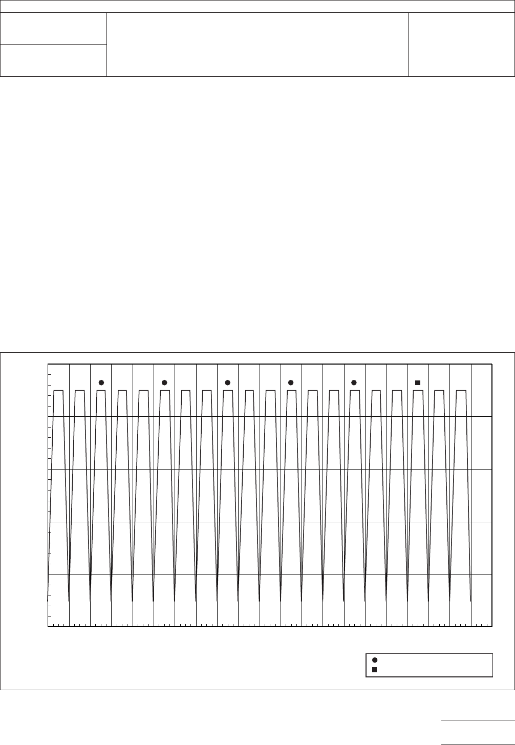
5.7.1.6 Expose test specimens to 20 cycles of temperature
and humidity (see Figure 2). The bias voltage shall be main-
tained throughout the entire 20-cycle period. Humidity shall be
maintained at 85% minimum through the cycles except when
going to low temperature (see step c below), in which case
the humidity may temporarily drop to 80% minimum.
One cycle is as follows:
a. Start test at 25±2°C[77±3.6°F]andraise the tempera-
ture to 65±2°C[149 °F] over a time span of 2.5 hours ±
5 minutes
Figure 2 Moisture and Insulation Resistance Test Graph
0
20
30
40
50
60
70
8 16 24 32 40 48 56 64 72 80 88 96 104 112 120 128 136 144 152 160 168
Elapsed Time (hour)
Temperature (Degree C)
Optional Measurement Made
Mandatory Measurement Made
IPC-TM-650
Number
2.6.3.1
Subject
Solder Mask - Moisture and Insulation Resistance
Date
03/07
Revision
E
Page3of5