IPC-TM-650 EN 2022 试验方法.pdf - 第351页
1.0 Scope This procedure determines vertical and horizon- tal slump for solder pastes. 2.0 Applicable Documents None 3.0 Test Specimen A standard specimen shall be pre- pared using a clean frosted glass microscope slide …

1.0
Scope
This
test method is designed to measure the
viscosity of paste flux.
2.0
Applicable Documents
None
3.0
Test Specimen
Enough
paste flux to fill a container
with a minimum diameter of 4 cm to a minimum depth of
approximately 10 cm.
4.0
Apparatus and Reagents
4.1
Brookfield
RVT viscometer or equivalent with helipath
stand and a TC spindle.
4.2
Water
bath capable of holding 25 +/-0.5°C.
4.3
Stopwatch
4.4
Spatula
5.0
Procedure
5.1
Test
5.1.1
Place
container of paste flux in water bath at 25+/-
0.5°C.
5.1.2
When
medium has attained thermal equilibrium, place
container under spindle so that it is at center of surface.
5.1.3
Start
the Brookfield at 5 revolutions per minute and
start the Helipath stand on descend.
5.1.4
Two
minutes after the spindle has cut into the top sur-
face of the medium, record the value. Check that spindle is
not touching bottom of container.
5.1.5
Remove
spindle from the paste flux. Using spatula, stir
the flux vigorously for 15 to 20 seconds and remeasure
viscosity.
5.2
Expression of Results
The
viscosities are calculated
from the values recorded after 2 minutes of medium penetra-
tion. Both stirred and unstirred results should be quoted.
6.0
Notes
6.1 Safety
Observe all appropriate precautions on MSDS
for chemicals involved in this test method.
The
Institute for Interconnecting and Packaging Electronic Circuits
2215 Sanders Road • Northbrook, IL 60062-6135
IPC-TM-650
TEST
METHODS MANUAL
Number
2.4.34.4
Subject
Paste
Flux Viscosity − T-Bar Spindle Method
Date
1/95
Revision
Originating Task Group
Flux Specifications Task Group (5-24a)
Material
in this Test Methods Manual was voluntarily established by Technical Committees of the IPC. This material is advisory only
and its use or adaptation is entirely voluntary. IPC disclaims all liability of any kind as to the use, application, or adaptation of this
material. Users are also wholly responsible for protecting themselves against all claims or liabilities for patent infringement.
Equipment referenced is for the convenience of the user and does not imply endorsement by the IPC.
P
age1of1
电子技术应用 www.ChinaAET.com
1.0
Scope
This
procedure determines vertical and horizon-
tal slump for solder pastes.
2.0
Applicable Documents
None
3.0
Test Specimen
A
standard specimen shall be pre-
pared using a clean frosted glass microscope slide measuring
7.6 cm x 2.5 cm, minimum 1 mm thick. An equivalent alumina
or glass epoxy substrate may be used.
4.0
Equipment/Apparatus
Stencils
IPC-A-21,
IPC-A-20
Steel Squeegee (razor blade)
Oven
Microscope
5.0
Procedure
5.1 Preparation
5.1.1
Specimen
preparation using appropriate stencil pat-
tern IPC-A-21 or IPC-A-20. (Figures1&2)Deposit solder
paste patterns on 2 substrates for each stencil pattern. The
T
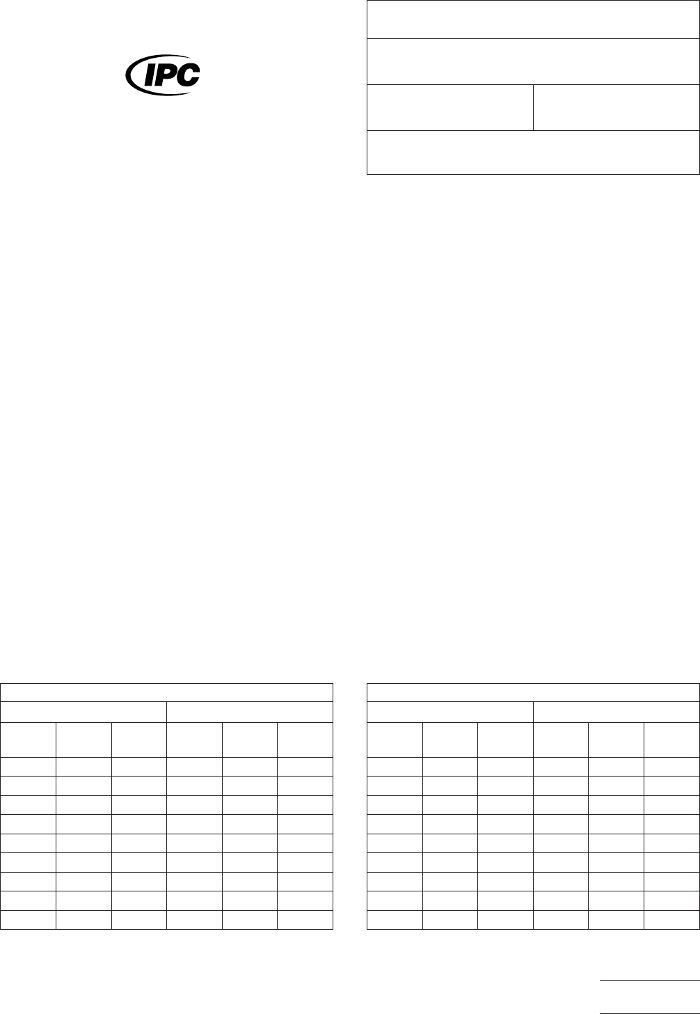
able 1
Stencil
IPC-A-21 (0.2 mm Thick)
Pad size 0.63 x 2.03 mm Pad size 0.33 x 2.03 mm
Spacing
mm Hor. Vert.
Spacing
mm Hor. Vert.
0.79
0.45
0.71 0.40
0.63 0.35
0.56 0.30
0.48 0.25
0.41 0.20
0.33 0.15
0.10
0.08
printed
pattern shall be uniform in thickness with no solder
particles separated from the pads. The vendor and user
should use the same printing method.
5.1.2 One
test specimen shall be marked as specimen #1
and one specimen as #2 and processed in accordance with
paragraphs 5.2.1 and 5.2.2.
5.2
Test
5.2.1
The
specimens shall be stored for 10 to 20 minutes at
25 +/–5°C and 50% relative humidity +/–10% and specimen
#1 examined for slump.
5.2.2
Specimen
#2 from 5.2.1 shall be heated to 150
+/–10°C for 10 to 15 minutes, cooled to ambient and exam-
ined for slump.
5.3
Evaluation
Enter
data in Table 1 and/or Table 2 by
entering spacings which have bridged with a suitable check
mark.
T
able 2
Stencil
IPC-A-20 (0.1 mm Thick)
Pad size 0.33 x 2.03 mm Pad sie 0.2 x 2.03 mm
Spacing
mm Hor. Vert.
Spacing
mm Hor. Vert.
0.45
0.30
0.40 0.25
0.35 0.20
0.30 0.175
0.25 0.15
0.20 0.125
0.15 0.10
0.10 0.075
0.08
The
Institute for Interconnecting and Packaging Electronic Circuits
2215 Sanders Road • Northbrook, IL 60062-6135
IPC-TM-650
TEST
METHODS MANUAL
Number
2.4.35
Subject
Solder
Paste—Slump Test
Date
1/95
Revision
Originating Task Group
Solder Paste Task Group (5-24b)
Material
in this Test Methods Manual was voluntarily established by Technical Committees of the IPC. This material is advisory only
and its use or adaptation is entirely voluntary. IPC disclaims all liability of any kind as to the use, application, or adaptation of this
material. Users are also wholly responsible for protecting themselves against all claims or liabilities for patent infringement.
Equipment referenced is for the convenience of the user and does not imply endorsement by the IPC.
P
age1of3
电子技术应用 www.ChinaAET.com
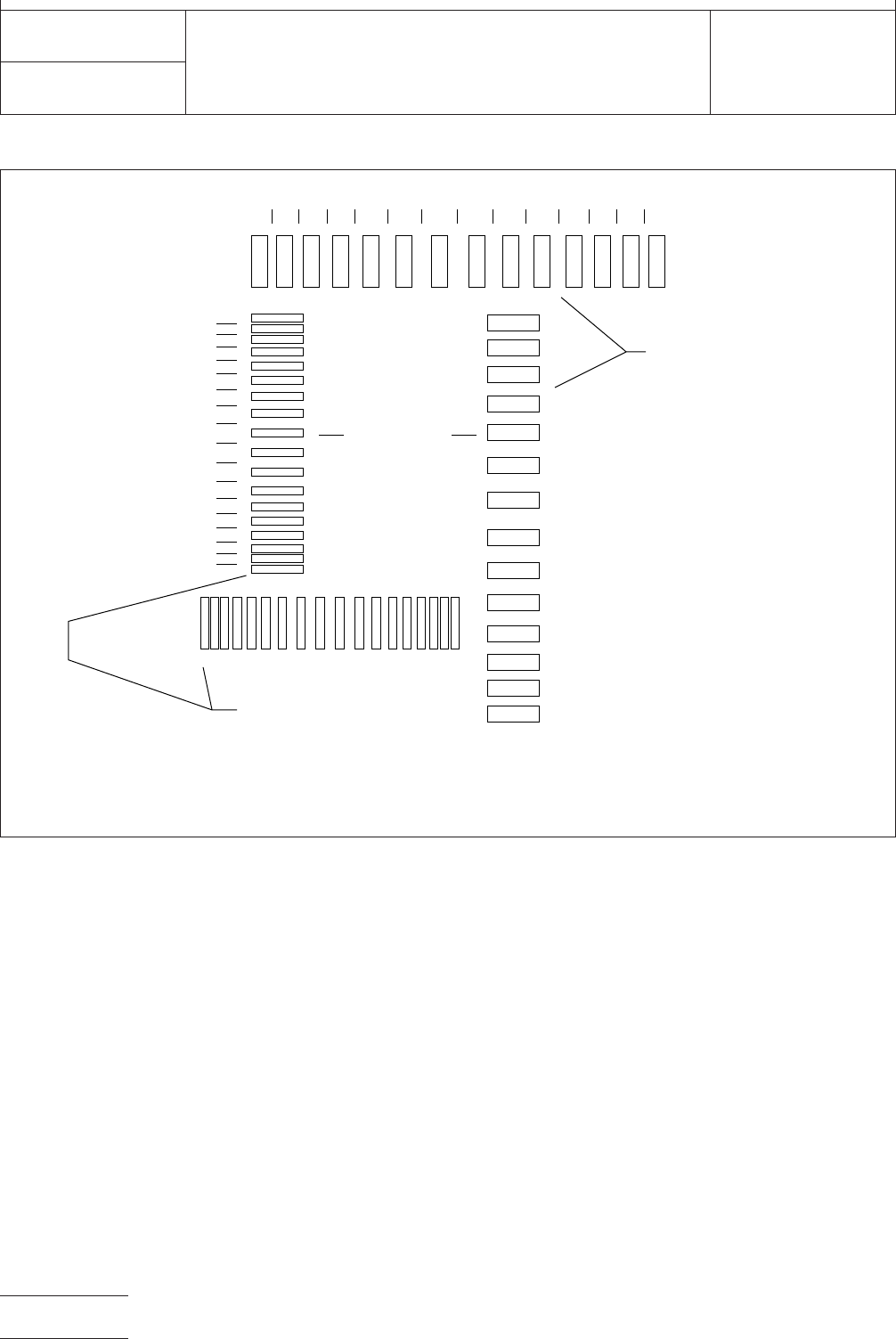
J-003060
Figure
1 Slump test stencil, IPC-A-21
▼
Spacing
▼
0.06 mm
▼
0.10 mm
▼
0.15 mm
▼
0.20 mm
▼
0.25 mm
▼
0.30 mm
▼
0.35 mm
▼
0.40 mm
▼
0.45 mm
▼
0.40 mm
▼
0.35 mm
▼
0.30 mm
▼
0.25 mm
▼
0.20 mm
▼
0.15 mm
▼
0.10 mm
▼
0.06 mm
Spacing
Vertical
Rows
▼
▼
▼
Pad Size:
0.33 x 2.03
mm
—18 identical pads per row
—Same spacings each row
▼
▼
Pad Size:
0.63 x 2.03
mm
—14 identical pads per row
—Same spacings each row
Spacing Spacing
▼
33mm
▼
.41
▼
.48
▼
.56
▼
.63
▼
.71
▼
.79
▼
.71
▼
.63
▼
.56
▼
.48
▼
.41
▼
.33mm
IPC-TM-650
Number
2.4.35
Subject
Solder
Paste—Slump Test
Date
1/95
Revision
P
age2of3
电子技术应用 www.ChinaAET.com