IPC-TM-650 EN 2022 试验方法.pdf - 第233页
1.0 Scope With this test method the flexural fatigue life for any given bend radius, the flexural fatigue behavior and the ductility of the conductor metal in percent deformation after tensile failure can be determined. …
1 Scope To determine the number of flexes to conductor
failure of etched flexible printed board conductor patterns.
2 Applicable Documents None
3 Test Specimen The test specimen shall consist of an
etched conductor pattern in accordance with Figure 1. A mini-
mum of six specimens with the long dimension of the conduc-
tors oriented in the transverse direction of the base material
shall be prepared using standard commercial practices.
For double-sided clad constructions, a separate sample
specimen shall be prepared for each side. The opposite
(untested) side shall be completely etched of copper.
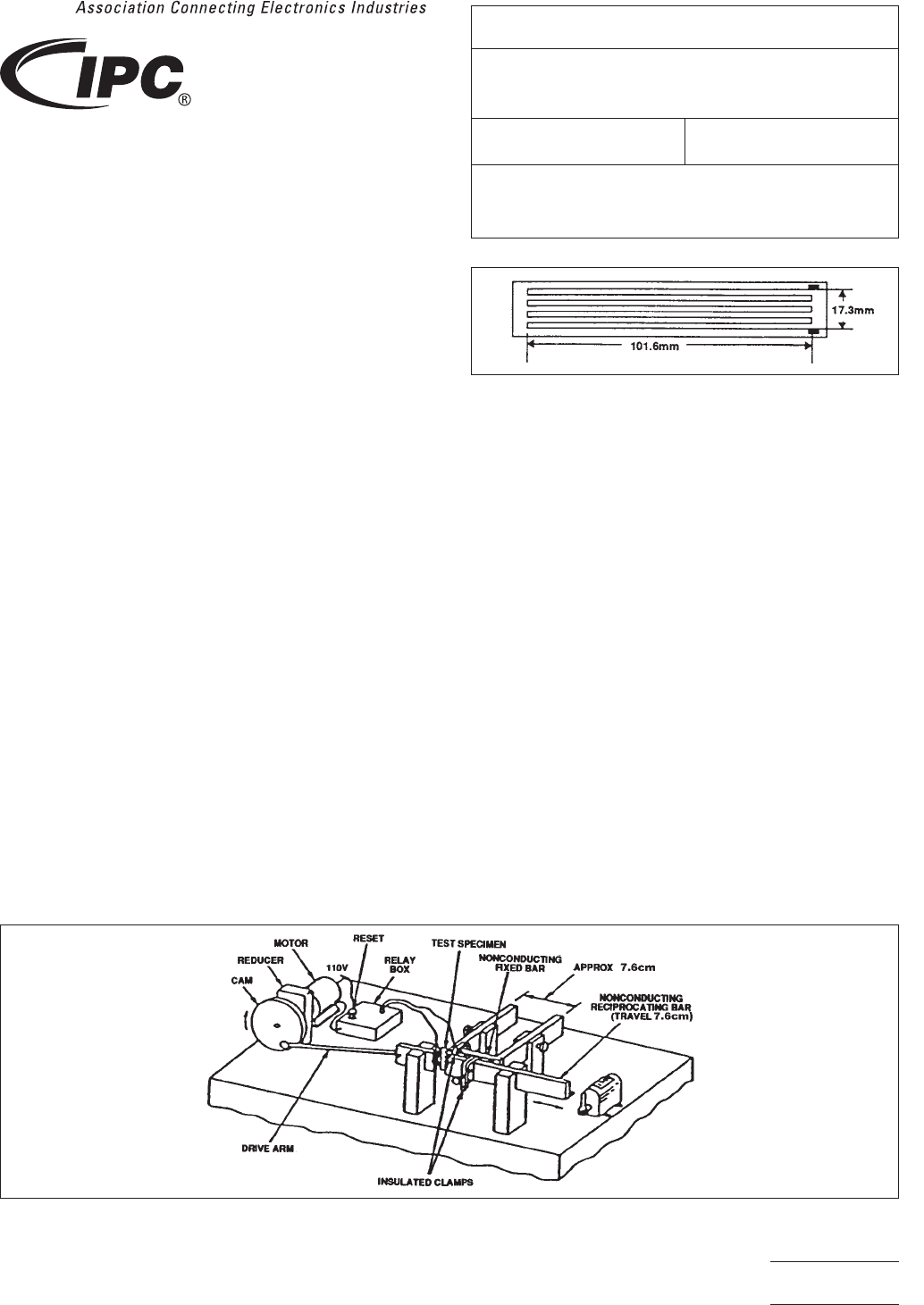
4 Apparatus Flexural Endurance Tester (see Figure 2) or
equivalent.
5 Procedures
5.1
Examine the etched conductor specimen for any pre-
existing fractures and look for evidence of process anomalies
(such as pin holes and nicks), which could cause premature
fracture. If such fractures or anomalies are found, the speci-
men shall be discarded and a new specimen selected.
5.2 Attach (solder, clamp, etc.) a short length of insulated
wire to the extreme ends of the conductor pattern of each of
the six specimens.
5.3 Using the flexure test equipment as seen in Figure 2,
mount the specimen so that the inside diameter of the loop is
6mm±1mm[approximately, 0.25 in ± 0.04 in] and connect
the two wires to the relay. The horizontal oscillation of the
reciprocating bar causes the flexible test specimen to move in
what can be described as a rolling, flexible action.
5.4 Test three specimens per clad side with the conductor
on the inside of the loop. The reciprocating travel should not
exceed 10 cycles per minute. The loop shall travel 25 mm ±
5 mm [effectively, 1 in ± 0.2 in].
5.5 The number of cycles to failure is when electrical discon-
tinuity of the conductor occurs.
5.6 Report the average number of cycles to failure for the
three specimens tested per clad side.
6 Note Master set of drawings of a similar test fixture as
seen in Figure 2 is available from the IPC office. This fixture is
not commercially available.
IPC-243-1
Figure 1 Flexural Endurance Test Pattern.
(NOTE: Conductors are 1.5 mm ± 0.1 mm [approximately, 0.059 in ±
0.004 in] wide on 2.5 mm ± 0.1 mm [approximately, 0.01 in ± 0.004 in]
centers.)
IPC-243-2
Figure 2 Typical Flexural Endurance Test Fixture Equipment
3000 Lakeside Drive, Suite 309S
Bannockburn, IL 60015-1249
IPC-TM-650
TEST METHODS MANUAL
Number
2.4.3
Subject
Flexural Endurance, Flexible Printed Board
Materials
Date
6/11
Revision
E
Originating Task Group
Flexible Circuits Test Methods Subcommittee
(D-15)
Material in this Test Methods Manual was voluntarily established by Technical Committees of IPC. This material is advisory only
and its use or adaptation is entirely voluntary. IPC disclaims all liability of any kind as to the use, application, or adaptation of this
material. Users are also wholly responsible for protecting themselves against all claims or liabilities for patent infringement.
Equipment referenced is for the convenience of the user and does not imply endorsement by IPC.
Page1of1
1.0
Scope
With
this test method the flexural fatigue life for
any given bend radius, the flexural fatigue behavior and the
ductility of the conductor metal in percent deformation after
tensile failure can be determined.
Note: The indirect determination of conductor ductility by
using a fatigue test is made necessary by the geometry and
dimensions of foil samples which make tensile elongation and
rupture tests inadequate for ductility determination.
2.0
Applicable Documents
IPC-TM-650
Method
2.1.1, Microsectioning
IPC-TM-650
Method
2.4.18, Tensil Strength and Elongation,
Copper Foil
IPC-D-330
IPC
Design Guide
3.0
Test Specimen
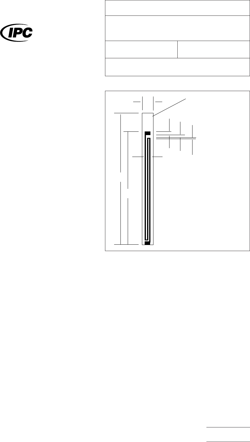
3.1
The
test coupon shown in Figure 1 is the recommended
standard test specimen pattern for either single- or double-
sided flexible printed wiring.
3.2
The
conductor width of the standard test pattern (Figure
1) can be changed to determine line width effects.
Note: Narrow conductor width will result in reduced flex lives
due to an increased flaw size/conductor width ratio. Wide
conductors result in increased flex lives due to longer crack
propagation times and the possibility of strain relief due to
cracks propagating in close proximity from opposite conduc-
tor edges.
3.3 Actual
flexible printed wiring product, whole or sections
thereof, can be used if the circuit geometry is such that the
long dimension is at least 63.2 mm [2.5 inches], the wide
dimension no more than 38.1 mm [1.5 inches], and the con-
ductors in the long direction can be electrically connected in
series to give a pattern similar to the standard test pattern (see
Figure 1).
4.0
Apparatus
4.1
Ductility
Flex Tester, Universal Mfg., Model FDF or 2FDF
or equivalent (see 6.4 and Figure 2).
4.2 Sample
cutter, punch or tensile cut router. Note 6.3.2.
4.3
Micrometer
tool capable of measuring 0.0025 mm
[0.0001 inch].
4.4
Hewlett-Packard,
HP-67, Programmable Calculator or
equivalent.
4.5
Sample
holders, 203.2 x 12.7 mm [8 x 1/2 inch] of very
flexible material, e.g., epoxy-impregnated glass cloth, paper,
etc.
4.6 Microscope
5.0
Procedure
5.1 Preparation of Samples
5.1.1
Use
the sample cutter to cut the 3.2 mm [1/8 inch]
wide test specimen. Examine each specimen for nicks, cuts,
or curled edges. Discard any specimen with defects.
IPC-2431-1
Figure
1 Test coupon configuration (recommended)
▼
▼
▼
▼
▼
▼
▼
▼
▼
▼
▼
▼
▼
45327
104mm
[4.10]
76.2mm
[3.00"]
NOTE 3
3.81mm [.150] (NOTE 1)
NOTES:
1. 0.76mm [.030"] Conductor width,
0.76mm [.030"] spacing
2. Pattern on opposite circuit
sides are identical
3. 5-digit lot number of
production lot.
▼
▼
2.54mm
[.100"] 12.7mm
[.050"] 12.7mm
[.050"]
88.9mm
[3.50"]
The
Institute for Interconnecting and Packaging Electronic Circuits
2215 Sanders Road • Northbrook, IL 60062-6135
IPC-TM-650
TEST
METHODS MANUAL
Number
2.4.3.1
Subject
Flexural
Fatigue and Ductility, Flexible Printed
Wiring
Date
3/91
Revision
C
Originating Task Group
N/A
Material
in this Test Methods Manual was voluntarily established by Technical Committees of the IPC. This material is advisory only
and its use or adaptation is entirely voluntary. IPC disclaims all liability of any kind as to the use, application, or adaptation of this
material. Users are also wholly responsible for protecting themselves against all claims or liabilities for patent infringement.
Equipment referenced is for the convenience of the user and does not imply endorsement by the IPC.
P
age1of3
电子技术应用 www.ChinaAET.com
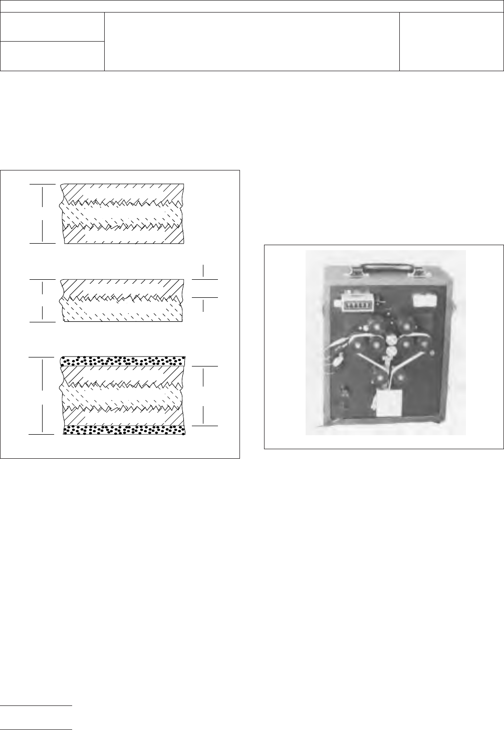
5.1.2
Use
the micrometer to determine the specimen thick-
ness, t, at the test region of the specimens to the nearest
0.0025 mm [0.0001 inch]. In the case of single-sided or
cover-coated specimens, core thickness, t
M
,
has to be deter-
mined also (see Figure 2).
Note: Thickness is a critical parameter in the determination of
fatigue ductility. A 10% error in t
M
results
in a 14% error in D
f
.
Note: For
asymmetric configuration (2nd configuration in Fig-
ure 2) the core thickness, t
M
,
is preferably determined as a
fraction of the specimen thickness, t, from a microsection pre-
pared per IPC-TM-650, Method 2.1.1, and measured with a
metallurgical microscope at 200X minimum with a suitable filar
eyepiece or reticle. The measurement is to be made from the
valley of the rough surface to the smooth surface or valley to
valley where both surfaces are rough. The t
M
is
to be made
once on a batch or lot basis, and this fractional value of t
M
/t
is
then multiplied by all other micrometer, t, values to achieve
core values for all samples. This applies only to the second
and third configuration in Figure 2, where t
M
cannot
be deter-
mined by a micrometer.
5.1.3
For
standard test coupons, connect the meander pat-
terns on opposite circuit sides in series and attach thin relay
leads to the free ends of the meander patterns. For nonstand-
ard test specimens, connect all conductors to be tested and
monitored in series and attach thin relay leads to the two free
ends.
5.1.4
Attach
test specimen to the ends of 2 sample holders
with adhesive tape and clamp 224 grams [8 ounces] circuit
weight to free ends of sample holders to form a loop (see Fig-
ure 3).
Note: For flexural fatigue tests lasting in excess of 1000
cycles, the adhesive tape attachment needs to be substantial
enough to prevent relative sliding of specimen and sample
holder as a result of the cyclic flexure movements.
5.2
Test Procedure
5.2.1
Mount
mandrels to flex tester, adjust the support roller
positions for a clearance of 1.27 mm [0.05 inches] (shim pro-
vided) between rollers and mandrels.
Note: For the ductility test, it is important that the specimens
fail between 30 and 500 cycles. Suggested mandrel diam-
eters are 19.05 mm [0.750 inch] for double-sided circuitry and
6.35 mm [0.250 inch] for single-sided circuitry, but for some
samples, mandrel diameters different from these diameters
may be necessary. Larger mandrel diameters result in longer
cyclic life and smaller diameters in shorter life.
IPC-2431-2
Figure
2 Minimum core thickness
t
COVERCOAT
COVERCOAT
▼
▼
M
▼
▼
t
▼
▼
t
M
▼
▼
t
▼
▼
t = t
M
SUBSTRATE
CONDUCTOR
CONDUCTOR
SUBSTRATE
CONDUCTOR
CONDUCTOR
CONDUCTOR
SUBSTRATE
IPC-2421-2
Figure
3 Fatigue ductility flex tester
IPC-TM-650
Number
2.4.3.1
Subject
Flexural
Fatigue and Ductility, Flexible Printed Wiring
Date
3/91
Revision
C
P
age2of3
电子技术应用 www.ChinaAET.com