IPC-TM-650 EN 2022 试验方法.pdf - 第503页
APPENDIX Example of the specimen preparation Figure A1 shows an example of three test specimens pre- pared from a free standing dielectric film. The dielectric was 25 µm thick. About 242 nm thick layer of gold was sputte…
from
metric units will lead to inherent accuracy and/or preci-
sion errors.
10
References
[
1] Fundamental Physical Constant, Permittivity,
http://
physics.nist.gov/cgi-bin/cuu/V
alue?ep0|search_for=permittivity
[2] M. A. Stuchly, S. S. Stuchly, ‘‘Coaxial line reflection meth-
ods for measuring dielectric properties of biological sub-
stances at radio and microwave frequencies: A review,’’
IEEE Trans. Instrum. Meas., vol. 29, pp. 176-183, 1980.
[3] N. Marcuvitz, Waveguide Handbook. McGraw-Hill, New
York: 1951.
[4] H. J. Eom, Y.C. Noh, J.K. Park, ‘‘Scattering analysis of a
coaxial line terminated by a gap,’’ IEEE Microwave Guided
Wave Lett., vol. 8, pp. 218-219, 1998.
[5] N.-E. Belhadj-Tahar, O. Dubrunfaut, A. Fourrier-Lamer,
‘‘Equivalent circuit for coaxial discontinuities filled with
dielectric materials - frequency extension of the Marcu-
vitz’s circuit’’ J. Electromagnet. Wave, vol. 15, pp. 727-
743, 2001.
[6] J. Obrzut, A. Anopchenko, ‘‘Input Impedance of a Coaxial
Line Terminated with a Complex Gap Capacitance -
Numerical and Experimental Analysis’’ IEEE Trans.
Instrum. Meas., vol. 53(4), Aug. (2004).
[7] ‘‘Mathematical Handbook for Scientists and Engineers,’’
G. A. Korn and T. M. Korn, McGraw-Hill, 2
nd
edition
(1968),
page 719.
11
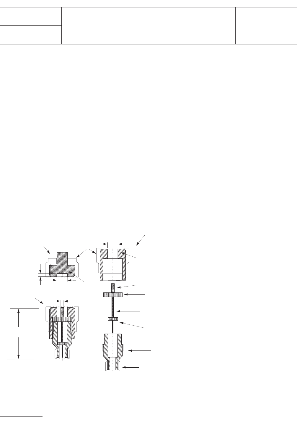
Test Fixture Drawings
IPC-25510-4
6
1 Center conductor pin
a
= 3.05 mm
2 Supporting dielectric in the APC-7 section
3 Center conductor in the APC-7 to APC-3.5
4 Supporting dielectric in the APC-3.5 section
5 APC-3.5 section of the adaptor
6 Section A outer conductor (
b
=7.00 mm)
7 Section B outer conductor (
b
=7.00 mm)
8 APC-7 mount
8
1
2
a
d
b
b
Section B
Section A
Section A details
Test Fixture for HF Permittivity of Embedded Passive Materials
Originator: IPC Embedded Passives Test Methods
3
4
5
50 Ω
Calibration Plane
METRIC, dimensions are in mm
7
APC-3.5 female mount
IPC-TM-650
Number
2.5.5.10
Subject
High
Frequency Testing to Determine Permittivity and Loss
Tangent of Embedded Passive Materials
Date
07/05
Revision
P
age6of8
电子技术应用 www.ChinaAET.com
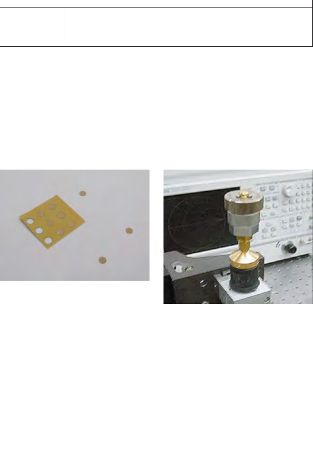
APPENDIX
Example
of the specimen preparation
Figure
A1 shows an example of three test specimens pre-
pared from a free standing dielectric film. The dielectric was
25 µm thick. About 242 nm thick layer of gold was sputtered
on both sides. A shadow mask with a pattern of circles hav-
ing each diameter of 2.9 mm was used to pattern the top sur-
face. The bottom surface was sputtered without masking. The
specimens were extracted from the film using a 3.0 mm
puncher.
Instrumentation
Example
Figure
A2 shows a photo of the assembled test fixture during
measurements. An APC-7 to APC-3.5 microwave adapter
(Agilent 1250-1746) is connected via a phase preserving
coaxial cable (Agilent 85131-60013) to a network analyzer. An
APC-7 short termination (Agilent 04191-85300), is attached
on top of the APC-7 to APC-3.5 adapter. The termination has
a custom machined gap to accommodate a specimen of a
particular thickness.
Figure
A1 Test specimens
Figure
A2 Test instrumentation
IPC-TM-650
Number
2.5.5.10
Subject
High
Frequency Testing to Determine Permittivity and Loss
Tangent of Embedded Passive Materials
Date
07/05
Revision
P
age7of8
电子技术应用 www.ChinaAET.com
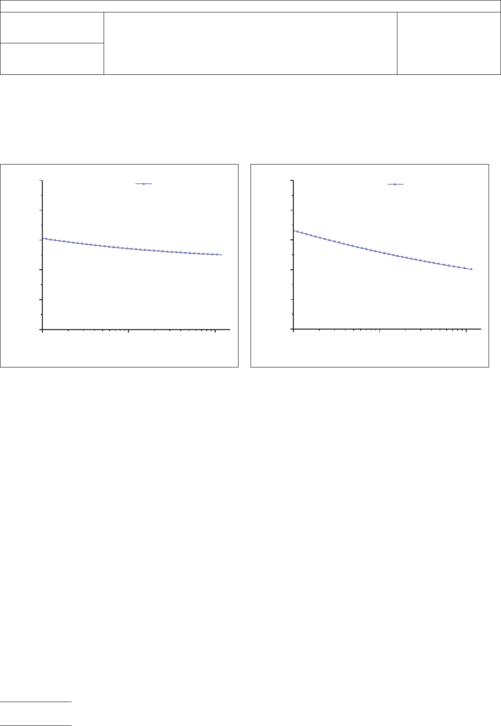
Example
measurement results
Figures
A3 and A4 illustrate the dielectric constant measurements from 100 MHz to 12 GHz performed according to the above
test method for typical low and high k materials. In the examples, the uncertainty increases with increasing frequency. The maxi-
mum relative uncertainty in the dielectric constant is about 5%. The standard deviation in the dielectric loss tangent is about 0.001.
Certain
equipment and instrumentation is identified in this document in order
to adequately specify the experimental procedure. This does not imply any
recommendations that these are the most suitable for that purpose.
IPC-25510-a-3
Figure
A3 Dielectric constant measured for a 25 µm thick
dielectric with a nominal dielectric constant value of 3.5.
1E8
1E9 1E10
3.50
3.52
3.54
3.56
3.58
3.60
k3.5
Dielectric Constant
Frequency / Hz
IPC-25510-4
Figure
A4 Dielectric constant measured for a 15 µm thick
dielectric with a nominal dielectric constant value of 11.
1E8
1E9 1E10
10.5
10.6
10.7
10.8
10.9
11.0
K11
Dielectric Constant
Frequency / Hz
IPC-TM-650
Number
2.5.5.10
Subject
High
Frequency Testing to Determine Permittivity and Loss
Tangent of Embedded Passive Materials
Date
07/05
Revision
P
age8of8
电子技术应用 www.ChinaAET.com