IPC-TM-650 EN 2022 试验方法.pdf - 第181页
1 Scope This test is used to determine the total ionic con- tent extractable from on, and absorbed within, the surface of printed wiring boards (PWBs), for the purposes of process control. The conductivity of the extract…

6.3.2 Determine the surface area per Section 3.
6.3.3 Calibration A precise quantity of sodium chloride
calibration solution is injected into a designated volume of the
test solvent mixture in the sample measurement cell. This is
done according to the calibration or verification instructions
provided by the manufacturer of the equipment being used.
6.3.4 Testing Once the system has been calibrated or veri-
fied in accordance with 6.3.3, the sample tank is filled as
directed by the procedures of the equipment manufacturer
and the test specimen is immersed in the tank. The minimum
starting resistivity for this type of equipment is machine
dependent. Use clean gloves when handling the samples to
be tested. Finger dirt contains ionic materials which may con-
tribute to spurious reading. During the course of the measure-
ment, the resistivity will fall continually as ionic material is
extracted into solution. If conductivity is being monitored, it will
initially be very low, rising continually as ionic material is dis-
solved from the sample. The test can be terminated when
there is no further change, in time, of the resistivity or conduc-
tivity function. This can be established electronically in most
commercially available equipment. The initial and final values
together with the volume of the solvent mixture in the test
tank, and sample surface area are used by the system to cal-
culate the ionic levels which were present on the sample sur-
face prior to the test.
6.3.5 Refer to the manufacturer’s equipment manual for
optimal operation.
6.4 Interpretation of Test Data See 5.4.
7 Notes
7.1 Temperature
Higher solution temperatures will result
in higher levels of extracted ionic material. Most machines
have calculation algorithms which incorporate the solution
temperature. Refer to the machine documentation to under-
stand how temperature affects the ionic contamination read-
ing.
For process control testing, temperature should be set at a
constant value for periodic measurements. All calibrations of
the equipment should be made at the same solution tempera-
ture used to run the test.
7.2 It is critical to always use test solution with the same
composition of electronic grade 2-propanol (isopropyl
alcohol)/DI water for all comparative data discussions.
7.3 It is also suggested that a solution blank of 5 mL of
2-propanol/DI water be run at time of calibration to determine
the foundational cleanliness of the testing system.
7.4 Specific pieces of test equipment only have contamina-
tion output displays of two digits, if results are greater than or
equal to 100 the actual results will be lost and only the last
two digits will be displayed.
7.5 An extremely ‘‘dirty’’ sample can exceed machine maxi-
mums. Refer to the equipment documentation to determine
the maximum reading of the instrument.
8 References
IPC-TM-650, Test Method 2.3.28
Ionic Analysis of Circuit
Boards by Ion Chromatography
IPC-TP-1113 Circuit Board Ionic Cleanliness Measurement:
What Does It Tell Us?
IPC-HDBK-001 Handbook and Guide to Supplement J-STD-
001
IPC-TM-650
Number
2.3.25
Subject
Detection and Measurement of Ionizable Surface Contaminants by
Resistivity of Solvent Extract (ROSE)
Date
11/12
Revision
D
Page5of5

1
Scope
This
test is used to determine the total ionic con-
tent extractable from on, and absorbed within, the surface of
printed wiring boards (PWBs), for the purposes of process
control. The conductivity of the extract solution is measured
and the results are expressed as sodium chloride equivalence
per unit area.
2
Applicable Documents
IPC-TM-650
Test
Method 2.3.25, Detection and Measure-
ment of Ionizable Surface Contaminants by Resistivity of Sol-
vent Extract (ROSE)
3
Test Specimens
The
test specimen may be any unpopulated PWB. The num-
ber of specimens depends on the process control plan or
product drawings/prints.
4
Apparatus or Material
•
An automated Resistivity of Solvent Extract (ROSE) tester
• Conductivity dip probe with appropriate meter with tem-
perature compensation
• Hydrometer (0.800 - 0.900) for ROSE tester calibration
• Thermometer for ROSE tester calibration
• Clean room (non-ionic) gloves or forceps
• KAPAK™ plastic bags or equivalents (see 6.9)
• Bag sealing equipment
• Water bath, capable of sustaining an 80°C ± 2°C [176°F ±
3.6°F] temperature
• Second water bath capable of sustaining a 25°C ± 1°C
[77°F ± 1.8°F] temperature
• Precision solvent measurement equipment, such as class A
pipettes
• Volumetric glassware
• Plastic ware - high density polyethylene, polymethylpentene
(polypentene) or equivalent.
• Extract solution: 25% v/v deionized water (18 MΩ-cm nomi-
nal resistivity), 75% v/v 2-propanol (electronic or HPLC
grade). No alternative solution or composition is allowed.
• Sodium chloride - reagent grade
• Analytical balance accurate to 0.0001 grams
W
ARNING: 2-propanol is a flammable material. The 2-propanol /
water mixture is also flammable. Exercise caution when using this
solution.
5 Procedure
5.1 Extraction
NOTE: Throughout
this procedure, do not touch the sample
boards with bare hands. Use the clean room gloves specified
or use clean forceps.
5.1.1
Calculate
the surface area of the PWB using:
Area
(in cm
2
)
= Length x Width x 2
5.1.2
Prepare
a volume of extract solution specified in 4.
5.1.3
Using
clean room gloves or clean forceps, place the
PWB into virgin KAPAK™ bags. Choose the bag size to give
at least an additional 2.5 cm [1.0 in] on each side of the board
to minimize the amount of extract solution used. Allow at least
an additional 5 cm [2.0 in] above the board top.
5.1.4
Using
a pipette or graduated cylinder, add a volume of
the extract solution into the bag. The amount will depend on
the area of the board surface. This usually varies from 0.8
mL/cm
2
[5.2
mL/in
2
]
up to about 3 mL/cm
2
[19
mL/in
2
].
For
example, a 10 cm x 11.5 cm [3.94 in x 4.53 in] board would
require about 100 mL of solution. The amount of solution
should just cover the board completely when most of the air
is forced out of the bag.
5.1.5
Force
most of the air from the bag and heat seal the
bag. This involves contact with a hot metal bar. Take reason-
able precautions to keep extract solution from contacting the
hot bar. Alternatively, the top of the bag may be folded over
and clipped shut.
5.1.6
Place
the bag(s) vertically in a water bath which has
stabilized at 80°C [176°F]. Make sure that the boards do not
float above the water line. Do not allow the water from the
bath to enter the bag or for extract solution to leak out of the
bag.
2215
Sanders Road
Northbrook, IL 60062-6135
IPC-TM-650
TEST
METHODS MANUAL
Number
2.3.25.1
Subject
Ionic
Cleanliness Testing of Bare PWBs
Date
October 2000
Revision
Originating Task Group
Bare Board Cleanliness Assessment Task Group
5-32c
Material
in this Test Methods Manual was voluntarily established by Technical Committees of IPC. This material is advisory only
and its use or adaptation is entirely voluntary. IPC disclaims all liability of any kind as to the use, application, or adaptation of this
material. Users are also wholly responsible for protecting themselves against all claims or liabilities for patent infringement.
Equipment referenced is for the convenience of the user and does not imply endorsement by IPC.
P
age1of4
ASSOCIA
TION CONNECTING
ELECTRONICS INDUSTRIES
®
电子技术应用 www.ChinaAET.com
5.1.7
Allow
the boards to extract in this manner for a period
of time of 60 ± 5 minutes.
5.1.8
Following the extraction of 5.1.7, remove the bags
from the water bath and allow the extract solution to cool for
at least 30 minutes, with the specimen still in the bag.
5.1.9
Using
clean tongs or forceps, remove the PWB from
the bag.
5.2
Measurement – DIP Probe Method
5.2.1 Calibration of Bridge
This
is essential in this method
because there can be no correlation between resistivity/
conductivity readings and NaCl equivalents without calibra-
tion.
5.2.1.1
Prepare
a standard NaCl solution from a weight of
dry reagent grade NaCl salt dissolved in deionized water to
produce a final diluted concentration of 0.06 g/liter NaCl (5 mL
equals 300 µg NaCl).
5.2.1.2
Place
1 liter of the 2-propanol water solution (at the
calibration temperature of the bridge in use) in a plastic bea-
ker.
NOTE: The 75 % v/v 2-propanol solution must be used in this
calibration. Water cannot be used since it is not the test solu-
tion used in the procedure. The test solution used in this cali-
bration can be recleaned by passing through the DI column
until the required resistivity/conductivity is obtained.
5.2.1.3 From
a 50 mL burette, add to the liter of test solu-
tion, 5 mL of the standard 0.06 g/liter NaCl solution. Stir and
measure resistivity/conductivity.
5.2.1.4
From
a 50 mL burette, add to the liter of test solu-
tion, 20 additional mL of the standard 0.06 g/liter NaCl solu-
tion, for a total of 25 mL. Stir and measure resistivity/
conductivity.
5.2.1.5
From
a 50 mL burette, add to the liter of test solu-
tion, 25 additional mL of the standard 0.06 g/liter NaCl solu-
tion, for a total of 50 mL. Stir and measure resistivity/
conductivity.
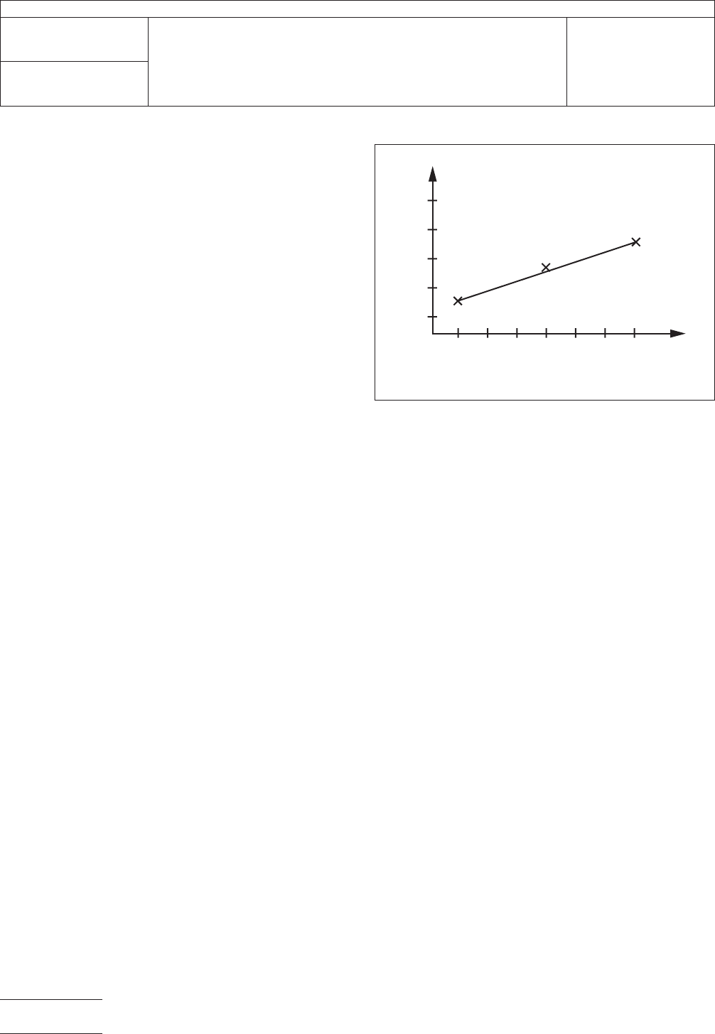
5.2.1.6
Plot
a three point nomogram of Conductivity vs.
Solution Concentration (in µg/liter NaCl). See Figure 1 for
example. You should get a linear relationship. Use a best fit
line obtained with a piecewise linear method.
5.2.2
Test Procedure - DIP Probe
NOTE: If
desired, this test can be run at other temperatures;
however, the calibration process must be repeated for the
alternative temperature. This calibration process need only be
done once, providing the conductivity cell has not been
exposed to harsh chemicals which would alter the cell con-
stants. If the conductivity cell is routinely used on harsh
chemical solutions (e.g., plating baths), then the calibration
should be repeated before every test run.
5.2.2.1
Place
the Kapak™ bags containing the extract solu-
tions into the 25°C [77°F] water bath and allow the extract
solutions to reach 25°C [77°F].
5.2.2.2
Insert
the conductivity probe into the Kapak™ bag
containing the room-temperature extract solution. It is impor-
tant that the extract solution be measured at the same tem-
perature used for the calibration solutions. Immerse the probe
to a suitable depth.
NOTE: A ‘‘suitable depth’’ is one which covers the cell elec-
trodes, but not an immersion which covers the wiring. Many
cells are marked with a scribed line which indicates the proper
immersion depth.
5.2.2.3
Gently
agitate the solution. Read the conductivity of
the solution. The time between immersion of the cell and tak-
ing the reading should be the same as used for the calibration
curve. Sufficient time should be allowed for the reading to
come to equilibrium (no change for two minutes).
IPC-2325-1
Figure
1 Nomogram of Conductivity vs. Solution
Concentration
Conductivity
Solution Concentr
ation
in micrograms NaCl/Liter
IPC-TM-650
Number
2.3.25.1
Subject
Ionic
Cleanliness Testing of Bare PWBs
Date
October 2000
Revision
P
age2of4
电子技术应用 www.ChinaAET.com