IPC-TM-650 EN 2022 试验方法.pdf - 第722页
1 Scope This test method provides a means to assess the propensity for surface electrochemical migration. This test method can be used to assess soldering materials and/or processes. 2 Applicable Documents 2.1 IPC IPC-B-…

a. Contamination on the insulating surface of the board such
as lint, solder splines, or water droplets from the condition-
ing chamber.
b. Incompletely etched patterns that decrease the insulating
space between conductors by more than the amount
allowed in the appropriate design requirements drawing.
c. Scratched, cracked or obviously damaged insulation
between conductors.
6 Notes
6.1
Protective coatings are helpful in preventing electro-
chemical migration, but there is no assurance that the protec-
tion is complete unless the coating is adequately bonded to a
good clean board.
IPC-TM-650
Number
2.6.14
Subject
Solder Mask - Resistance to Electrochemical Migration
Date
03/07
Revision
D
Page4of4
1
Scope
This
test method provides a means to assess the
propensity for surface electrochemical migration. This test
method can be used to assess soldering materials and/or
processes.
2
Applicable Documents
2.1 IPC
IPC-B-25
Multipurpose
Test Board
IPC-B-25A
Multipurpose
Test Board
IPC-6012A
Qualification
and Performance Specification for
Rigid Printed Boards
IPC-9201
Surface
Insulation Resistance Handbook
2.1
American Society for Testing and Materials (ASTM)
ASTM D-257-93
Standard
Test Methods for DC Resistance
or Conductance of Insulating Materials
3
Test Specimens
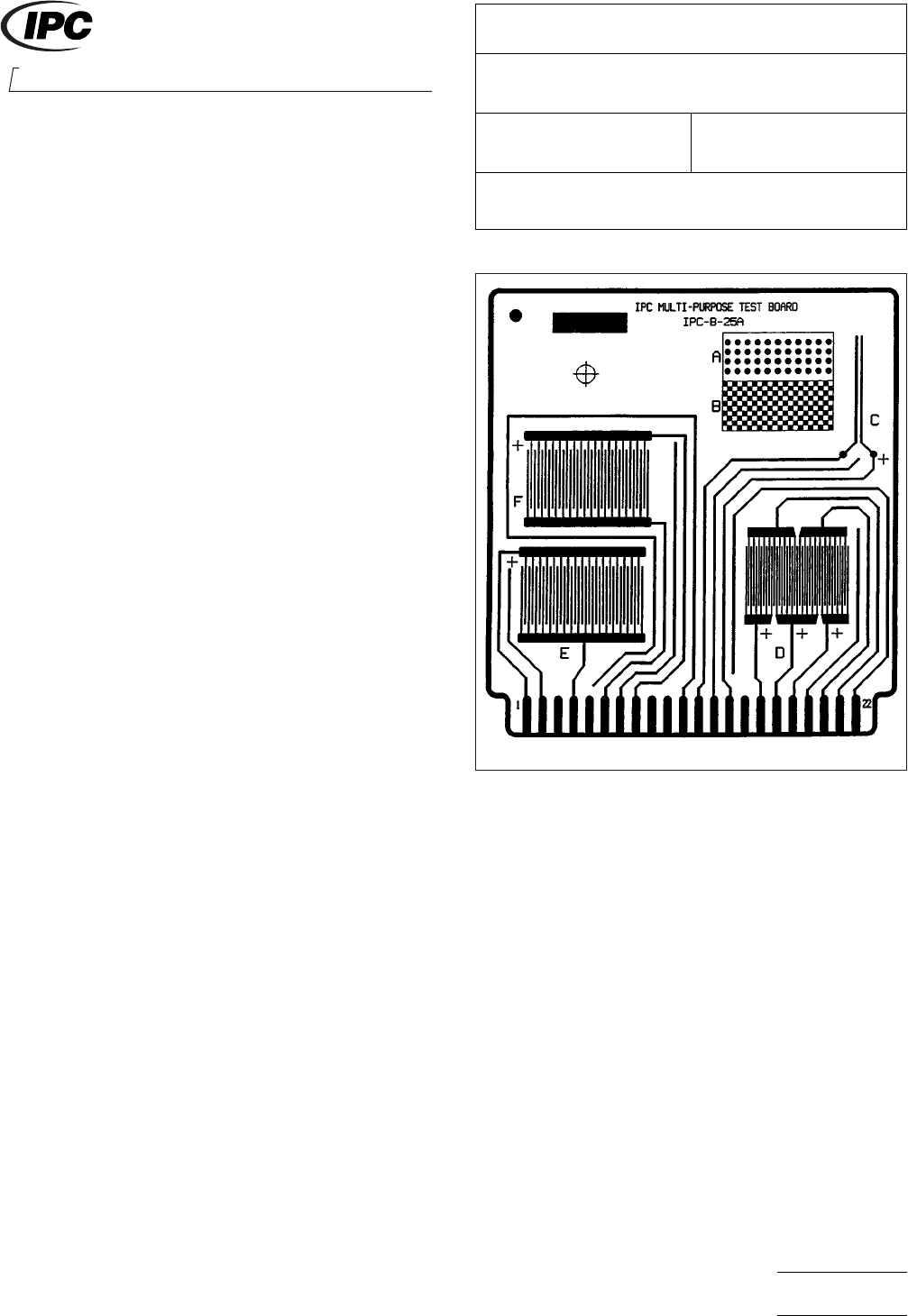
IPC-B-25
(B or E pattern) or IPC-B-25A
(D pattern) test boards shall be used, with conductor line
widths and spacings of 0.318 mm [0.01250 in]. The method
of manufacture should provide optimized conductor edge
definition (refer to the Class 2 and 3 conductor width require-
ments in IPC-6012). The finished test boards should be
untreated, bare copper, unless another surface finish is part of
the evaluation. Figure 1 shows the IPC-B-25A test board; the
D pattern is identical to the IPC-B-25 B or E pattern. For pro-
cess evaluation, the test pattern board should be made using
the same substrate material as will be used in practice to
duplicate actual working conditions.
4
Equipment/Apparatus
4.1 Test Chamber
A
temperature/humidity chamber
capable of producing an environment of 40°C ± 2°C [104 ±
3.6°F], 93% ± 2% RH, 65°C ± 2°C [149 ± 3.6°F], 88.5% ±
3.5% RH, or 85°C ± 2°C [185 ± 3.6°F], 88.5% ± 3.5% RH
and allowing test boards to be electrically biased and mea-
sured without being opened under these temperature and
humidity conditions is used.
4.2
Measuring Equipment
High
resistance measuring
equipment, equivalent to that described in ASTM D-257-93,
with a range up to 10
12
ohm
and capable of yielding an accu-
racy of ± 5% at 10
10
ohm
with an applied potential of 100 VDC
(10% tolerance); standard resistors should be used for routine
calibration.
4.3
Power Supply
Equipment
capable of providing 10
VDC at 100 µA, with a 10% tolerance, shall be used.
4.4
Current-Limiting Resistors
Use
one 10
6
ohm
resistor
in each current path. This equates to three current-limiting
resistors for each 5-point comb pattern. Note that some test
equipment has the current limiting resistors built into the test-
ing system.
4.5
Connecting Wire
Use
PTFE-insulated, solid-
conductor, copper wire, or equivalent. (See IPC-9201 Surface
Insulation Resistance Handbook.)
IPC-26141-1
Figure
1 IPC-B-25A Test Board
2215
Sanders Road
Northbrook, IL 60062-6135
IPC-TM-650
TEST
METHODS MANUAL
Number
2.6.14.1
Subject
Electrochemical
Migration Resistance Test
Date
09/00
Revision
Originating Task Group
Electrochemical Migration Task Group
Material
in this Test Methods Manual was voluntarily established by Technical Committees of IPC. This material is advisory only
and its use or adaptation is entirely voluntary. IPC disclaims all liability of any kind as to the use, application, or adaptation of this
material. Users are also wholly responsible for protecting themselves against all claims or liabilities for patent infringement.
Equipment referenced is for the convenience of the user and does not imply endorsement by IPC.
P
age1of3
ASSOCIA
TION CONNECTING
ELECTRONICS INDUSTRIES
电子技术应用 www.ChinaAET.com

4.6
Other Dedicated Fixtures
Hardwiring
is the default
connection method. Other dedicated fixtures may be used,
provided that the fixture does not change the resistance for
more than 0.1 decade compared to a comparable hardwired
system, when measured at the test conditions.
5 Procedure
5.1 Test Specimen Preparation
5.1.1
In
performing a material qualification (e.g., flux), all
specimens are to be cleaned and dried using a process
capable of yielding a minimum insulation resistance value of
4x10
10
ohm
when tested at 35°C, 85% minimum RH after
24 hours. If this test is being performed as a process qualifi-
cation, additional pre-test processing is not allowed.
5.1.2 A
minimum of three test specimens cleaned per 5.1.1
shall be used for controls.
5.1.3
For
liquid flux:
Apply the liquid flux to the entire surface of the test specimen
by brushing liberal quantities of the flux onto the specimen, by
floating the specimen comb side down on the liquid flux, or by
dipping the specimen into the flux. The specimen shall be
drained vertically for one minute with the fingers of the comb
pattern vertical. Alternatively, flux may be applied by produc-
tion application processes - spray, foam, or wave. The edge
connector fingers should be protected from flux.
It is recommended that production wave soldering equipment
be used for soldering the test specimens, with a preheat pro-
file representative of production. A solder fountain may be
used (not a solder pot), with a residence time similar to the
residence time in a solder wave. Solder composition is usually
60% tin ± 5%, remainder is lead; for such alloys, the solder
temperature shall be 250°C ± 6°C [482 ± 10.8°F]. For alloys
other than those with compositions near the tin-lead eutectic,
the solder temperature will be compatible with the usual sol-
dering temperature for the alloy used.
If any solder bridging occurs, that specimen shall be dis-
carded. A minimum of three specimens from the sample
group shall be tested.
5.1.4
For
solder paste:
A squeegee or screen printer shall be used with a stencil
imaged with the test pattern. It should be noted that the Tel-
cordia GR-78 pattern requires a minimum stencil thickness of
0.20 mm [7.9 mil]. Due to the fact that the minimum stencil
thickness is often dependent on the pitch or trace width and
spacing, a smaller stencil thickness may be used for fine fea-
tures and shall be agreed upon between the tester and cus-
tomer for the purpose of this test method.
Reflow the printed specimens using convection, infrared, or
vapor phase reflow equipment using a reflow profile represen-
tative of production. Equivalent methods may be used if such
equipment is not available.
If any solder bridging occurs, that specimen shall be dis-
carded. The edge connector fingers should be protected from
paste.
A minimum of three specimens from the sample group shall
be tested.
5.1.5
For
flux-cored wires:
Using a hand soldering iron and the cored wire under test,
carefully apply solder to the fingers of all comb patterns. The
edge connector fingers should be protected from flux.
If any solder bridging occurs, that specimen shall be dis-
carded.
A minimum of three specimens from the sample group shall
be tested. Each circuit path will be tested for the presence of
solder shorts using a resistance meter (e.g. digital multimeter).
5.1.6
Post
solder cleaning shall be performed only when
such cleaning is part of the production process used in the
final assembly.
5.1.7
When
evaluating incoming board quality and/or final
finishes, test specimens shall be used as received or as speci-
fied by the end user.
5.1.8
Attach
test leads to the land areas of all patterns either
by mechanical pressure (e.g., edge connectors, spring-loaded
pins) or by hand soldering using Rosin (R) cored wire, using a
shield to protect the test patterns from flux contamination dur-
ing soldering; the flux shall not spread into the pattern area.
Do not remove the flux.
5.2
Test Procedure
5.2.1
Place
the terminated test specimens in a suitable rack
that maintains the specimens at least 2.5 cm apart and such
that the air flow is parallel to the direction of the test speci-
mens in the chamber. For hardwiring, wires should be
IPC-TM-650
Number
2.6.14.1
Subject
Electrochemical
Migration Resistance Test
Date
09/00
Revision
P
age2of3
电子技术应用 www.ChinaAET.com