IPC-TM-650 EN 2022 试验方法.pdf - 第137页
4.8 Flame Gauging Device A thin steel scale template for gauging flame height 4.9 Burner Base A block support for use as a burner base with a 20° incline for proper positioning of the burner flame under the sample 5 Proc…

1
Scope
This
test method is intended to evaluate the rela-
tive flame resistance characteristics of a permanent solder
mask coating on specified printed wiring laminates. It is
intended for use on laminate 0.5 mm thick and greater. It
should indicate to what degree, if any, that the coating may
diminish the flammability of the laminate. The performance
level of a material by these methods should not be assumed
to correlate with its performance in end-use applications.
2
Applicable Documents
IPC-TM-650 Test Method Manual
2.3.6
Etching, Ammonium Persulfate Method
2.3.7 Etching, Ferric Chloride Method
2.3.7.1 Cupric Chloride Etching Method
3
Test Specimen
3.1
Test
specimens shall be prepared using vendor recom-
mendations or manufacturers’ production process and fabri-
cated parallel to either the warp or the fill direction as conve-
nient.
3.2 Test
specimens shall be 130 mm±5mminlength and
13 mm ± 0.5 mm in width by the thickness being tested.
Metal cladding shall be removed by etching, using IPC-TM-
650, Test Method 2.3.6, 2.3.7, or 2.3.7.1.
3.3
The
solder mask coating shall be applied evenly at both
the minimum and maximum anticipated coating thickness
over both the minimum and maximum laminate thickness
desired.
3.4
All
of these specimen sets, as well as one specimen set
of uncoated laminate, for each laminate thickness, should
come from the same laminate lots. In addition, if other solder
masks are to be compared, all should be applied to the same
lots, or results can vary widely. Pretesting of laminate lots is
recommended.
3.5
Edges
may be smoothed after fabrication, providing that
any radius imparted to the corners does not exceed 12.5 mm.
3.6 Five
specimens shall be prepared for each condition
required (two conditions—see specimen conditioning).
Reserve duplicates of five specimens are also required in the
event a retest is necessary. Total specimens per set are there-
fore equal to 20. Total sets required, including uncoated sub-
strate, would be six.
Note:
Additional
coatings tests would not have to include the
uncoated sets if the laminate lots are the same and submitted
simultaneously.
4
Apparatus
4.1 Test Chamber
A
laboratory hood, totally enclosed,
with a heat resistant glass window for observing the test, shall
be used. The exhaust fan shall be turned off during the test,
but may be turned on periodically to clear out the fumes and
carbonized airborne particles between tests.
4.2
Clamping Devices
A
clamping device, adjustable for
vertical positioning of the test specimen, shall be provided
within the test chamber so the specimen will hang with its
length in a vertical position approximately coincident with the
central vertical axis of the test chamber.
4.3
Laboratory Burner
A
Bunsen or Tirrell Burner shall be
used having a tube length of 100 mm and an inside diameter
of 9.4 mm ± 1.5 mm. The burner shall not be equipped with
end attachments.
4.4
Gas Supply
The
gas supply shall be regulated and
metered for uniform flow. The standard gas shall be technical
grade methane. Natural gas having a nominal heat content of
1000 BTU per cubic foot may be substituted. Other fuel
gases, such as butane, propane, and acetylene may be used;
however, technical grade methane will be used for referee
testing.
4.5
Timing Device
A
stop watch or other suitable timing
device with a precision of 0.5 seconds minimum
4.6
Desiccator
A
desiccator containing dried silica gel or
calcium chloride
4.7
Circulating Oven
A
conditioning oven of circulating
draft type capable of maintaining 70°C ± 1°C
The
Institute for Interconnecting and Packaging Electronic Circuits
2215 Sanders Road • Northbrook, IL 60062-6135
IPC-TM-650
TEST
METHODS MANUAL
Number
2.3.10.1
Subject
Flammability
of Soldermask on Printed Wiring
Laminate
Date
8/98
Revision
Originating Task Group
N/A
Material
in this Test Methods Manual was voluntarily established by Technical Committees of the IPC. This material is advisory only
and its use or adaptation is entirely voluntary. IPC disclaims all liability of any kind as to the use, application, or adaptation of this
material. Users are also wholly responsible for protecting themselves against all claims or liabilities for patent infringement.
Equipment referenced is for the convenience of the user and does not imply endorsement by the IPC.
P
age1of4
电子技术应用 www.ChinaAET.com
4.8
Flame Gauging Device
A
thin steel scale template for
gauging flame height
4.9
Burner Base
A
block support for use as a burner base
with a 20° incline for proper positioning of the burner flame
under the sample
5
Procedure
5.1 Specimen Conditioning
5.1.1
Specimen
sets should first be brought to room tem-
perature (23°C ± 2°C) for 24 hours prior to being thermal
shocked within the specifications of both the laminate and
solder mask being tested.
5.1.2
Specimen
sets shall then be divided into two groups
of 10 each. The first group shall be conditioned prior to test-
ing by exposure to standard laboratory conditions of 23°C
± 2°C and RH of 50% ± 5% for a minimum of 48 hours.
The first set shall be referred to as ‘‘as received’’ specimen.
5.1.3
The
second group shall be conditioned for a duration
of 168 hours (seven days) at 70°C ± 1°C and then cooled in
a desiccator over anhydrous calcium chloride for at least four
hours at room temperature (23°C ± 2°C) prior to testing.
This second set shall be referred to as ‘‘conditioned’’ speci-
men.
5.1.4
From
each of these groups, one half (five specimens)
will be burned for the evaluation, with the remaining five speci-
mens being held in reserve for retest if needed.
Note:
See
5.6 to determine if and when the reserve sets will
be needed.
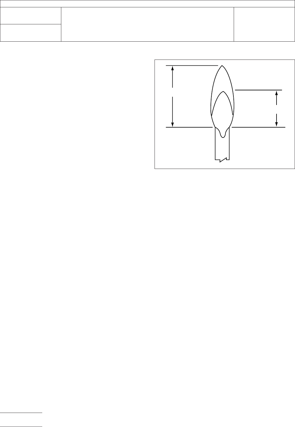
5.2
Adjustment of Test Flame
The
burner is ignited and
adjusted to produce a blue flame 19 mm high. The correct
flame is obtained by adjusting the gas supply and the air ports
of the burner until a blue flame with a yellow tipped outer cone
19 mm high is produced. The air supply is increased slightly
by opening the air ports until only the yellow tip just disap-
pears and it forms completely blue inner and outer flame
cones. The flame is remeasured to assure correct height. The
procedure is repeated as necessary until all conditions are
met. The burner tube is vertical during the adjustment and
measuring (see Figure 1).
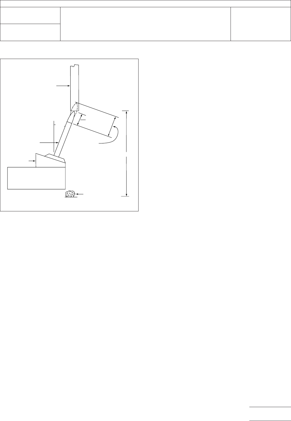
5.3
Specimen Mounting
Each
specimen is mounted in the
test fixture with its longitudinal axis vertical. The clamp used
shall cover no more than the upper 6.5 mm of the specimen.
The vertical position of the test fixture/specimen assembly is
adjusted so that the lower end of the specimen is 9.5 mm
above the top of the burner tube (see Figure 2).
5.4
Flame Test
The
test flame is placed centrally under
the lower end of the specimen. Timing begins immediately for
10 ± 0.5 seconds. The burner is withdrawn at least 152 mm
away from the specimen. If active combustion ceases prior to
the specimen being completely consumed, the test flame is to
be immediately placed under the specimen again for an addi-
tional 10 ± 0.5 seconds, then withdrawn as before.
5.5
Data to be Observed and Recorded
The
following
test data is to be recorded:
a. Duration of specimen burning to the nearest second after
the first test flame application for each specimen
b. Duration of specimen burning to the nearest second after
the second test flame application for each specimen
c. Duration of specimen burning plus glowing to the nearest
second after the second test flame application for each
specimen, only if required by the specification
d. If any specimen burns up to the holding clamp on any igni-
tion
e. If any specimen drips flaming particles, and if they ignite
the dry absorbent surgical cotton located 305 mm below
the test specimen
IPC-23101-1
Figure
1 Burner Flame
19 mm
9.5 mm
IPC-TM-650
Number
2.3.10.1
Subject
Flammability
of Soldermask on Printed Wiring Laminate
Date
8/98
Revision
P
age2of4
电子技术应用 www.ChinaAET.com
f.
Calculation of the total specimen burning time or the aver-
age specimen burning time as applicable based on 10 igni-
tions per set of five specimens (see Figure 3)
g. Calculation of the glowing time for each specimen if
required by the specification
5.6
Evaluation and Reporting
The
material shall be con-
sidered to be out of compliance with the specification if:
a. More than one specimen per set burns up to the holding
clamp on any ignition
b. More than one specimen per set burns for a period of time
longer than allowed by the specification for a single speci-
men
c. The total specimen burning time as applicable exceeds the
maximum allowed by the specification and is beyond the
tolerance specified in 5.6.2
d. More than one specimen glows for a period of time greater
than allowed by the specification (when applicable)
e. More than one specimen drips flaming particles, which
ignite the dry absorbent surgical cotton
5.6.2
Reporting
Each
test condition is reported separately.
The parameters outlined in 5.6 are to be reported only as
applicable.
5.6.3
Retests
If
only one specimen per set (five) fails to
comply with the requirements, the reserve set of specimen
shall be tested. In the case of total and/or average specimen
burning time, the reserve set shall be tested only if these cal-
culated values exceed the specification maximum by five sec-
onds or less. All specimens, their total, and their average from
the reserve set shall comply with the requirements.
6 Notes
6.1
The
inside of the burner barrel should be cleaned fre-
quently. Specimen combustion by-products can collect
around and inside the barrel tip. These deposits can be
flushed out during burner ignition and flame adjustment,
resulting in a false yellow flame tip. Proper flame adjustments
then become very difficult if allowed to remain.
6.2
When
the flame is correct and the specimen’s end is at
the proper height above the burner (9.5 mm), the inner blue
cone of the flame will just meet the end of the specimen. The
hottest area of the flame will then ignite the specimen.
6.3
Accurate
centering of the flame under the specimen is
essential for consistent test results.
IPC-23101-2
Figure
2 Specimen Mounted in the Test Fixture
Specimen
9.5 mm
19 mm
304 mm
Dr
y absorbant
surgical cotton
Mounting
Block
Burner
20
o
IPC-TM-650
Number
2.3.10.1
Subject
Flammability
of Soldermask on Printed Wiring Laminate
Date
8/98
Revision
P
age3of4
电子技术应用 www.ChinaAET.com