IPC-TM-650 EN 2022 试验方法.pdf - 第266页
IPC-249-5 Figure 5 Failure Modes with Adhesiveless Metal Foil Polyimide Film Start Metal = P olyimide Failure to Metal F oil PS = P olyimide Shatter Force (Chart Record) Metal PS IPC-TM-650 Number 2.4.9 Subject Peel Stre…
IPC-249-4
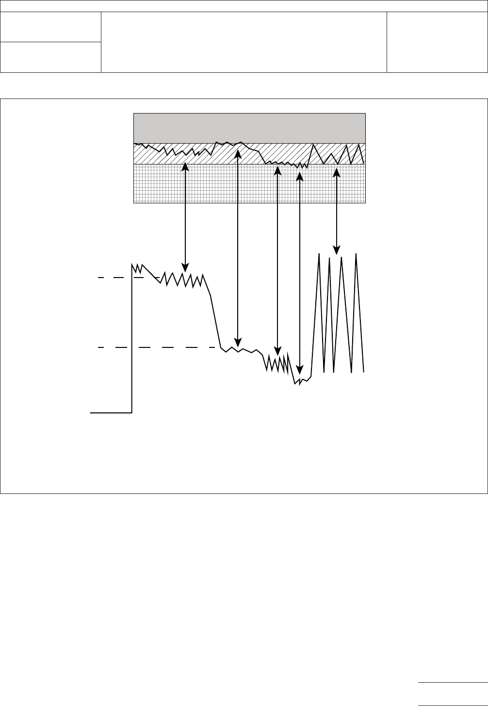
Figure 4 Typical Failure Modes with Adhesive
NOTE: Zipper failure (also termed Slipstick failure): A peel failure that propagates faster than the crosshead speed and oscillates from
the interface between the adhesive layer and the metal foil through the cohesive layer of the adhesive itself to the adhesive interface
with the dielectric film and into the dielectric film where it fails cohesively and reverses this failure. It also exhibits itself by peel strengths
that vary widely from a gradual build to a maximum peel value to a nearly instantaneous drop to no peel value at all in a cyclic manner.
Metal Foil
Adhesive Layer
Polyimide Film
Force
(Chart Record)
Start
CA
Metal
P
PS
Z
Zippered
Effect
CA = Cohesive Failure within Adhesive Layer
Metal = Adhesive Failure to Metal Foil
P = Adhesive Failure to Polyimide Film
PS = Polyimide Shatter
Z = Zipper Failure within Adhesive Layer (surface-to-surface)
IPC-TM-650
Number
2.4.9
Subject
Peel Strength, Flexible Dielectric Materials
Date
04/14
Revision
E
Page5of6
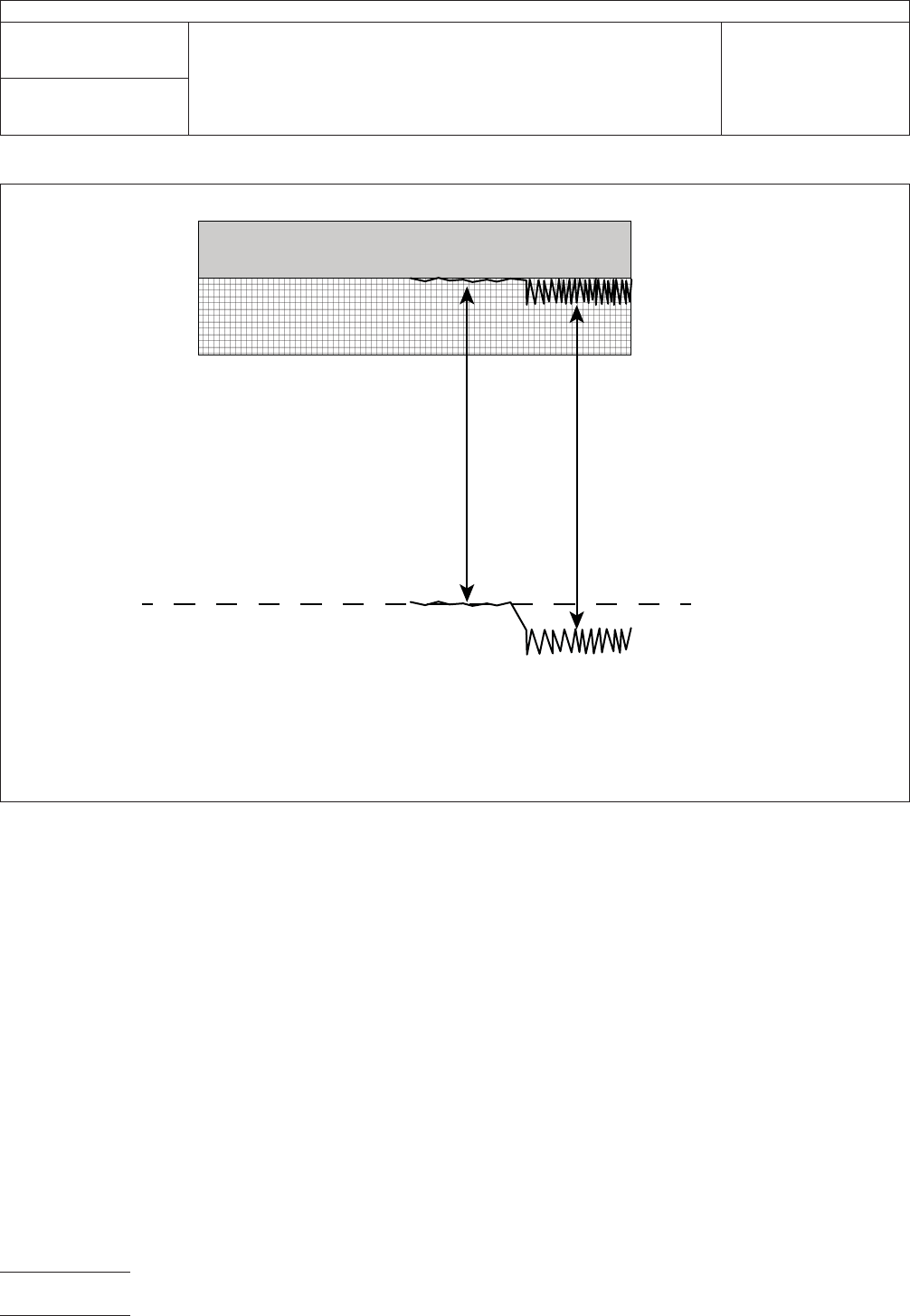
IPC-249-5
Figure 5 Failure Modes with Adhesiveless
Metal Foil
Polyimide Film
Start
Metal = Polyimide Failure to Metal Foil
PS = Polyimide Shatter
Force
(Chart Record)
Metal
PS
IPC-TM-650
Number
2.4.9
Subject
Peel Strength, Flexible Dielectric Materials
Date
04/14
Revision
E
Page6of6
1
Scope
The
purpose of this test is to characterize peel
adhesion at ambient conditions.
2
Applicable Documents
IPC-3408
General
Requirements for Anisotropically Con-
ductive Adhesive Films.
3
Test Specimens
3.1
1
mm pitch (center-to-center) flex test circuits and 1 mm
pitch (center-to-center) test boards
4
Apparatus
4.1
Soda-lime
glass test slides or printed circuit boards
4.2
All
other test materials listed in IPC-3408
4.3
‘Instron-1122’
tensile tester or equivalent, equipped with
air-powered jaws and 50 kg load cell, adjustable to 10 kg full
scale
4.4
Test
fixture, mountable on lower stage of tensile tester
5
Procedure
5.1 Sample Preparation
5.1.1
Cut
flex test circuits to the appropriate length (see Fig-
ure 1).
5.1.2
Use
of new PCBs is recommended. If new boards are
being used there should be no need for any special cleaning
procedure. If used boards are to be used, they should be
inspected to ensure that:
a) Protective metalization (Au or Pb-Sn) is intact,
b) FR-4 isn’t significantly discolored from prior high tempera-
ture exposure,
c) The board is free of any residue from previous tests.
5.1.3
Refer
to IPC-3408 for proper bonding procedure.
5.2
Procedure
5.2.1
Prepare at least three, and preferably five, samples for
each test point to be measured.
5.2.2
Confirm
proper calibration of the tensile tester, and
ensure proper full-scale setting.
5.2.3 Mount
sample in test fixture. Secure the flex circuit tail
into the air-powered jaws on the cross-head stage, being
careful to place the jaws as close to and as square to the
bond-line as possible.
5.2.4
Peel
the sample at a rate of 2.5 mm/min., and record
the peak adhesion value.
5.2.5
Repeat
steps 3 and 4 for all additional samples. Com-
pute the average adhesion value and record.
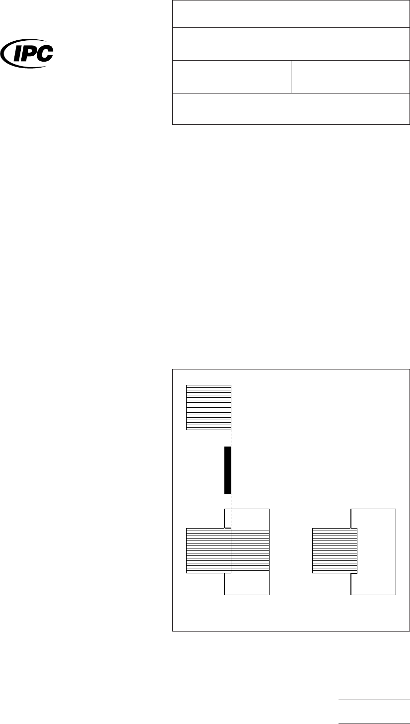
IPC-3408-fig1
Figure
1 Sample Pattern
1 mm Pitch Flex, 17 traces
20 mm x 20 mm
ACF, 0.050 mm, 3.2 mm x 20 mm
a) Flex-Board
b) Flex-Glass
The
Institute for Interconnecting and Packaging Electronic Circuits
2215 Sanders Road • Northbrook, IL 60062-6135
IPC-TM-650
TEST
METHODS MANUAL
Number
2.4.9.1
Subject
Peel
Strength of Flexible Circuits
Date
11/98
Revision
Originating Task Group
SMT Mounting Adhesives Task Group (5-24d)
Material
in this Test Methods Manual was voluntarily established by Technical Committees of the IPC. This material is advisory only
and its use or adaptation is entirely voluntary. IPC disclaims all liability of any kind as to the use, application, or adaptation of this
material. Users are also wholly responsible for protecting themselves against all claims or liabilities for patent infringement.
Equipment referenced is for the convenience of the user and does not imply endorsement by the IPC.
P
age1of1
电子技术应用 www.ChinaAET.com