IPC-TM-650 EN 2022 试验方法.pdf - 第279页
1.0 Scope A test method for measuring the geometric irregularities (roughness, waviness, etc.) of the surface of metal foils. 2.0 Applicable Documents None 3.0 Test Specimen Any sample of metal foil to be tested. Care mu…

addition,
the method can help evaluate fluxing power on criti-
cal applications prior to manufacturing operations.
6.1
Safety
Observe all appropriate precautions on MSDS
for chemicals involved in this test method.
6.2
Correction for Buoyancy
For the results from different
wetting balance tests to be relatable, it is necessary to correct
for the variability in specimen sizes. This is done by correcting
the zero axis for the buoyant force produced by the volume of
sample immersed in the solder. (The instrument zero corrects
for the weight of the specimen.) The following formula is used
to calculate the magnitude of the buoyant force correction,
P
b
,
in µN: P
b
= ρ gV
Where:
ρ =
Density of solder @ 245°C (8.15g/cm
3
)*
g
= Acceleration of gravity (9810 mm/s
2
[386.220
in/
2
])
V
= Immersed volume of coupon (cm
3
)
v
= width x thickness x immersion depth)
*For Sn60/Pb40 Alloy
The calculated buoyancy force must be used to correct the
zero axis. This correction is required to obtain correct values
of wetting times as well as wetting forces. All measurements
of wetting times and wetting forces must be made from the
corrected zero axis. In the case of an upright (tensile force)
curve, the corrected zero axis will be below the instrument
zero, as shown in Figure 2.
Note: The vertical (tensile) force measured by the wetting bal-
ance consists of three forces – the weight of the specimen,
the buoyancy force, and the wetting force caused by the sur-
face tension of the solder and its interaction with the fluxed
coupon.
The weight of the specimen is constant, and is included in the
instrument zero axis.
The buoyancy force is equal to the weight of the solder dis-
placed when the specimen is immersed. It changes as the
specimen is lowered into and removed from the solder, but
may be considered constant during the dwell time.
The only changing force during the dwell time is the wetting
force. Changes in this force are caused by the contact angle
changing from initial nonwetting to wetting, as the specimen
solders. The corrected zero (buoyancy) line is the force when
the contact angle is 90°, or when the bath surface has
returned to horizontal, having been initially depressed by the
immersed sample. When the contact angle is 90°, the contri-
bution of the wetting force to the total vertical force is 0.
The wetting balance curve is centered on the corrected zero
(buoyancy) line, since the only parameter that changes during
the test dwell time is the contact angle, θ. The measured ver-
tical tensile force, F, in µN (omitting the constant weight of the
specimen, which is zeroed out by the instrument), is given by:
F=γρcos θ -gρv
Where:
γ = Surface tension of molten solder (400 µN/mm)
p = Specimen perimeter in mm
θ = Contact angle
g = Gravitational acceleration (9.81 x 10
3
mm/s
2
)
ρ =
Solder density (~8000 µg/mm
3
)
v
= Immersed volume in mm
3
The
buoyancy is the value of F when θ is 90° (cos θ = 0):
Buoyancy = -gρv
The corrected zero line (buoyancy) is the fixed reference point
for wetting force and wetting time measurements.
Altering the specimen dimensions changes the immersed vol-
ume and hence the buoyancy, and so alters the position of
the corrected zero line; but the wetting curve still remains
centered on this line. Similarly, any change in immersion depth
will also alter the immersed volume, with the same effect on
the buoyancy.
Although use of the corrected zero line will cancel small varia-
tions in the specimen immersed volume and the immersion
depth, large changes will affect the rate of heat transfer into
the specimen, which will affect both Tw, the time to recross
the corrected zero (buoyancy) line, and the time to reach
Fmax.
IPC-TM-650
Number
2.4.14.2
Subject
Liquid
Flux Activity, Wetting Balance Method
Date
06/04
Revision
A
P
age3of3
电子技术应用 www.ChinaAET.com

1.0
Scope
A
test method for measuring the geometric
irregularities (roughness, waviness, etc.) of the surface of
metal foils.
2.0
Applicable Documents
None
3.0
Test Specimen
Any
sample of metal foil to be tested.
Care must be taken to insure that there are no wrinkles or
kinks in the sample.
4.0
Apparatus
4.1
Amplimeter,
with range selector for measuring surface
roughness in micro inches.
4.2
Pilotor
(electric) used to operate the tracer.
4.3
Tracer,
for tracing and detecting surface irregularities.
4.4
Controlled
Roughness Specimen
4.5
Surface
Plate
5.0
Procedure
5.1 Test
5.1.1
Place
the amplimeter on a rigid support such as a
work bench, stand, or machine table with space beside it for
the pilotor that will be used.
Note:
Do
not connect the amplimeter to a power line supply-
ing heavy induction equipment such as induction furnaces,
welders and induction motors. The starting and stopping of
such equipment will cause fluctuations in the AC line voltage
which may result in erroneous roughness readings.
5.1.2
Set
the AA/RMS selector switch at AA (for arithmetical
average), and turn on amplimeter.
5.1.3
Check
setup for minimum vibration.
1. Position the tracer with an appropriate skidmount in place
on the work surface. Do not try to use the tracer without a
skidmount.
2. With the tracer stationary and the pilotor cable discon-
nected read the amplimeter digital display. If the reading is
higher than the work allows, move the setup to a steadier
support and repeat the check.
3. The displayed reading should not be greater than 10% of
the roughness to be measured.
5.1.4
Set
the roughness-width cutoff at 0.030 inch.
5.1.5
Set
the ‘‘Range’’ selector switch.
5.1.6
Set
the pilotor stroke length between 1 in. and 1.5 in.
5.1.7
To
make sure that the equipment in paragraph 4.0 is
operating properly, take a reading of the rated roughness
specimen.
Note:
The
controlled roughness specimen must be thoroughly
cleaned before it is used. A dirty specimen will give erroneous
readings.
5.1.8
If
erroneous display readings are obtained, check the
following conditions:
1. Amplimeter is turned on.
2. Tracer is connected to the amplimeter with all connections
tight.
3. Tracer is moving over the work.
4. Tracer point is in contact with the work.
5. Check the tracer cable for wear and for open or short cir-
cuits.
6. Check for a blown fuse in the amplimeter.
5.2
Evaluation
Record
roughness readings in micro inches
using Arithmetical Average (AA). A minimum of 3 areas per
sample should be taken for determining the surface rough-
ness.
The
Institute for Interconnecting and Packaging Electronic Circuits
2215 Sanders Road • Northbrook, IL 60062-6135
IPC-TM-650
TEST
METHODS MANUAL
Number
2.4.15
Subject
Surface
Finish, Metal Foil
Date
3/76
Revision
A
Originating Task Group
N/A
Material
in this Test Methods Manual was voluntarily established by Technical Committees of the IPC. This material is advisory only
and its use or adaptation is entirely voluntary. IPC disclaims all liability of any kind as to the use, application, or adaptation of this
material. Users are also wholly responsible for protecting themselves against all claims or liabilities for patent infringement.
Equipment referenced is for the convenience of the user and does not imply endorsement by the IPC.
P
age1of1
电子技术应用 www.ChinaAET.com
1 Scope This method covers the determination of the force
required to initiate tearing in flexible insulating materials. It is
based on ASTM D1004.
2 Applicable Documents
ASTM D374
Standard Test Methods for Thickness of Solid
Electrical Insulation
ASTM D1004 Standard Test Method for Tear Resistance
(Graves Tear) of Plastic Film and Sheeting
3 Test Specimens
3.1
The specimens shall be prepared using flexible dielec-
tric material. If the flexible dielectric is clad, the copper foil
shall be etched using standard commercial practices.
3.2 Ten specimens, five in the transverse and five in the lon-
gitudinal (machine) directions, shall be cut from the sample
material.
3.3 The test specimens shall conform to the dimensions
shown in Figure 1.
4 Test Equipment
4.1 Testing Machines
A power driven machine of either of
the two following types shall be used.
4.1.1 Static Weighing Constant rate of grip separation
type, negligible movement of the upper jaw.
4.1.2 Pendulum Weighing Constant rate of grip motion
type, constant rate of lower jaw movement, variable upper jaw
movement. Either maximum load indicating devices or record-
ers are permissible in the testing machine. The applied load,
as indicated by a recorder, dial or scale, shall be accurate to
within 12 percent. If an indicating device is used, the indicator
shall remain at the point of maximum load after rupture of the
test specimen.
4.2 Grips A gripping system that minimizes both slippage
and uneven stress distribution on the specimen shall be
used.
4.3 Thickness Measuring Devices Suitable calibrated
ratchet/friction thimble machinist’s micrometer reading to
0.0025 mm [0.0001 in] or less shall be used for measuring
the thickness of the specimens. The micrometer shall con-
form to ASTM D374.
4.4 Die A die having the dimensions shown in Figure 1
shall be used to cut all specimens. The 90° angle shall be
honed sharp with no radius or have a minimum practical
radius, as per ASTM D1004. The cutting edge of the die shall
have a 5° negative rake, and shall be kept sharp and free
from nicks to avoid leaving ragged edges on the specimen.
Cutting may be facilitated by wetting the surface of the sample
and cutting edges of the die with water. The sample shall rest
on a smooth, slightly yielding surface that will not injure the die
blade. Lightweight cardboard or a piece of leather belting is
suitable. Care should be taken that the cut edges of the speci-
men are perpendicular to its other surfaces and that the
edges have a minimum of concavity. NOTE: The test speci-
men results depend on the quality of the die used.
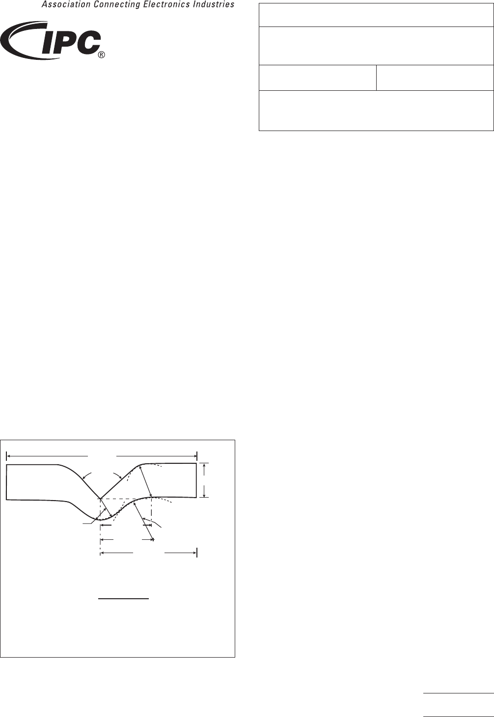
IPC-2416-1
Figure 1 Die for Tear Test Specimen
101.60mm
26.95mm (x2)
25.40mm radius (x2)
Dimensional tolerances ±0.051mm [0.002 in]
Table of Metric-to-Imperial Equivalents
in.
4.0
0.750
1.061
1.000
1.118
2.0
0.500
101.60
19.05
26.95
25.40
28.40
50.80
12.70
mm
28.40mm (x2)
50.80mm (x2)
19.05mm (x2)
19.05mm
radius (x2)
12.70mm radius (x2)
90º±0.5º
3000 Lakeside Drive, Suite 309S
Bannockburn, IL 60015-1249
IPC-TM-650
TEST METHODS MANUAL
Number
2.4.16
Subject
Initiation Tear Strength, Flexible Insulating
Materials
Date
03/14
Revision
B
Originating Task Group
Flexible Circuits Test Methods Subcommittee
(D-15)
Material in this Test Methods Manual was voluntarily established by Technical Committees of IPC. This material is advisory only
and its use or adaptation is entirely voluntary. IPC disclaims all liability of any kind as to the use, application, or adaptation of this
material. Users are also wholly responsible for protecting themselves against all claims or liabilities for patent infringement.
Equipment referenced is for the convenience of the user and does not imply endorsement by IPC.
Page1of2