IPC-TM-650 EN 2022 试验方法.pdf - 第593页
These readings are taken with both open and short circuits on the radiating bare wire. 6.4 It should be noted that although a shield may be quite effective in protecting a cable system, tests should be made to determine …

Induction
fields are either high- or low-impedance fields. A
high-impedance field is defined as a field whose impedance is
higher than the impedance of the dielectric in which it exists.
A low-impedance field has an impedance lower than the
impedance of the dielectric. High-impedance fields are asso-
ciated with a voltage source and most of their energy is con-
tained in their electric component, while low-impedance fields
are associated with a current source and most of their energy
is contained in the magnetic component.
1.2.2
Shield Impedance
An
important parameter associ-
ated with these radiating fields is the characteristic imped-
ance, which is the ratio of the electric to magnetic field com-
ponents. For a plane wave in free space, the characteristic
impedance is 377 ohms, and correspondingly for intense
electric or high impedance fields, it is greater than 377 ohms,
and for strong magnetic or low impedance fields, it is less than
377 ohms. The difference in characteristic impedance
between an incident field and a shield is directly proportional
to the reflection losses. The characteristic impedance of a
shield varies with the material’s permeability, conductivity, and
frequency. Shield impedances are generally low at low fre-
quencies and increase directly with frequency. Since at all fre-
quencies, electric (E) fields are high impedance and magnetic
(H) fields are low impedance, the corresponding reflection
losses are high for electric fields at low test frequency and low
or poor for magnetic fields at the same test frequency. As test
frequencies increase, the impedance mismatches decrease
for electric fields (decrease in R
E
)
and increase for magnetic
fields (increase in R
H
).
The absorption losses for both electric
and magnetic fields increase with frequency. It can be con-
cluded from this that good shielding effectiveness against pre-
dominantly electric fields can be obtained with most high con-
ductivity shielding materials. At low frequencies, R
E
losses
are
so high that small absorption losses may be neglected and, at
high frequencies, even though most of the transmitted energy
is coupled to the shield, absorption losses are high enough for
adequate shielding if all nonconductive openings in the shield
are eliminated. Shielding against magnetic fields presents a
different situation at low frequencies, where absorption and
reflection (R
H
)
losses are small. Here, uniform 100% shielding
is essential and in most cases ferromagnetic, highly perme-
able materials are employed to increase absorption losses. At
high frequencies, both reflection and absorption losses are
high, and shielding effectiveness is good for magnetic fields.
Table 1 shows properties of various metals at 150 KHz and
400 MHz and the corresponding absorption loss in db. The
significance of this table is to show the necessity for highly
permeable materials to shield against low frequency magnetic
fields.
3
Test Specimen
None
4
Equipment/Apparatus
None
5
Procedure
None
6 Notes
6.1
Shielding
effectiveness is usually determined more pre-
cisely by measurement than by calculation, especially when
100% shielding is impractical. To obtain the attenuation capa-
bility of a shielding material about a flat cable, it is more prac-
tical to test a cable system for its susceptibility to radiated
energy.
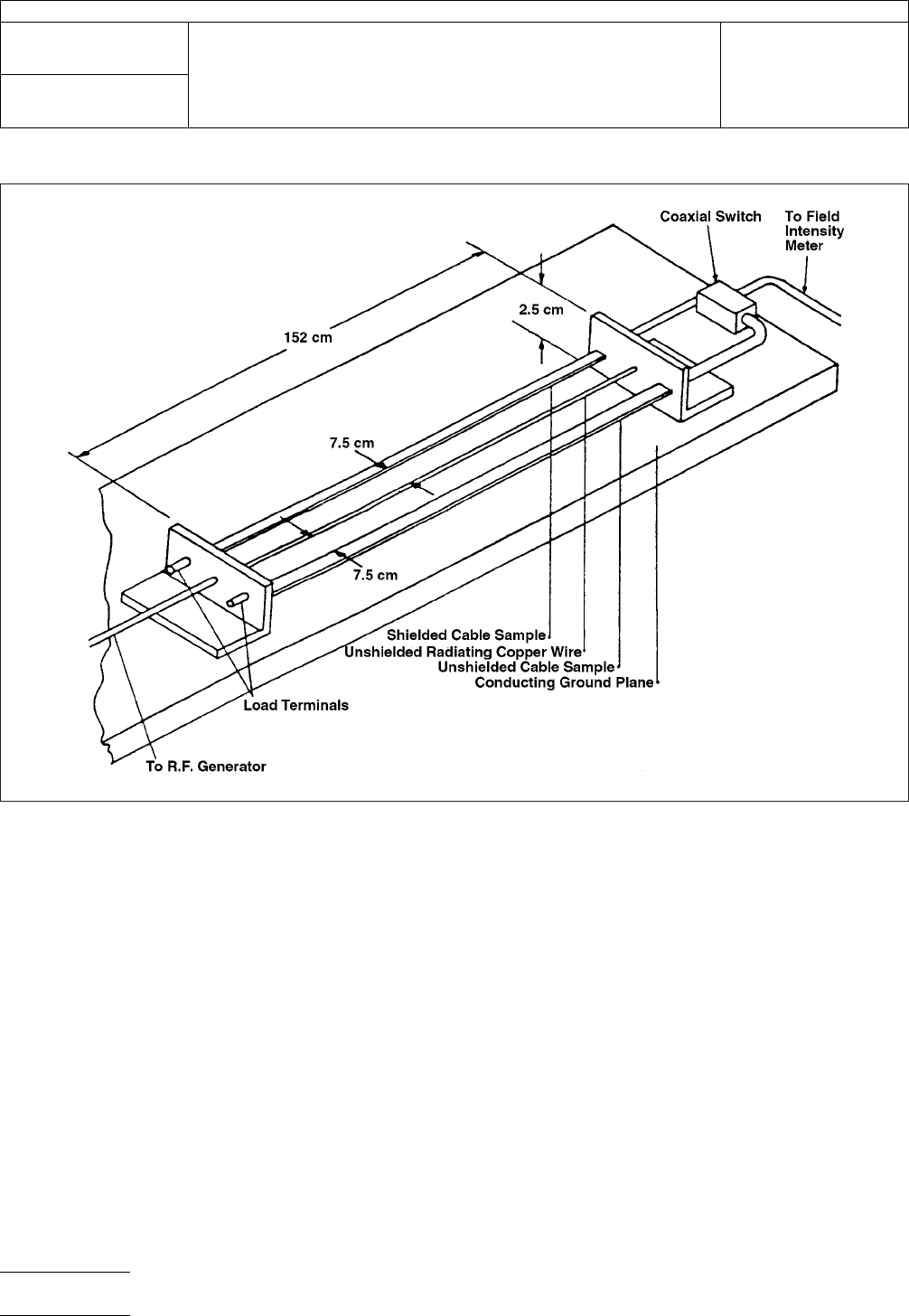
Figure 1 shows a test setup designed to measure shielding
effectiveness in a flat cable for electric and magnetic radiating
fields. Two 1.5 m cable specimens, one shielded and one
unshielded, are terminated in their characteristic impedance at
the generator source end and attached through a coaxial
switch to a field intensity meter (or similar device) at the other
end. These two cable samples are mounted and suspended
2.5 cm above a conducting ground plane and 7.5 cm to either
side of a bare unshielded copper wire (see Figure 2). This
radiating copper wire is connected at one end to a RF signal
generator and is terminated at the opposite end in either a
short or non-radiating open circuit.
6.2
When
the bare wire is open circuited, the majority of the
radiated field is electric, and when it is short circuited, mag-
netic fields dominate. Since the cables are only 7.5 cm away
from the radiating source, electric and magnetic shielding
effectiveness can be measured separately at frequencies up
to approximately 4 GHz. It is assumed that if a shield is effec-
tive under these conditions, it will be equally effective against
plane wave radiation.
6.3
Four
readings must be taken at each test frequency.
First the voltage pick-up in the unshielded specimen is
observed and is used as the reference level for the voltage
measurement on the shielded line. The shielding effectiveness
in decibels is given by:
S=20logV
u
/V
s
where:
V
u
=
voltage induced into unshielded cable
V
s
=
voltage induced into shielded cable
IPC-TM-650
Number
2.5.15
Subject
Guidelines
and Test Methods for RFI-EMI Shielding of Flat Cable
Date
10/86
Revision
A
P
age2of5
电子技术应用 www.ChinaAET.com

These
readings are taken with both open and short circuits on
the radiating bare wire.
6.4
It
should be noted that although a shield may be quite
effective in protecting a cable system, tests should be made
to determine the affect the shielding materials have on the
internal electrical cable properties.
In a cable system handling high-speed digital pulses, the
choice of shielding materials can greatly affect important
transmission characteristics. If a shield is applied to suppress
strong magnetic fields and a ferromagnetic material is used,
which has a low conductivity, it will create a direct capaci-
tance coupling between adjacent signal carrying conductors.
This coupling will cause an increase in the crosstalk between
signals and will also distort the output rise time of the pulse.
If shielding is necessary on a sophisticated transmission line
system, a few tradeoffs might be necessary to obtain the opti-
mum operating conditions.
T
able 1
Metal
Relative
Conductivity
G
Relative
Permeability
u
Properties
of Various Metals
at 150 KHz
Properties of Various Metals
at 400 MHz
Absorption
Loss in db
A
Magnetic
Reflection
Loss in db
R
H
Electric
Reflection
Loss
in db
R
E
Absorption
Loss
in db
A
Magnetic
Reflection
Loss in db
R
H
Electric
Reflection
Loss
in db
R
E
Silver
1.05 1 1.34 34.7 198.5 6.92 48.9 155.7
Copper 1.00 1 1.31 34.5 198.3 6.76 48.7 155.5
Gold 0.70 1 1.09 32.9 196.7 5.65 47.1 154.0
Aluminum 0.61 1 1.02 32.4 196.1 5.28 46.6 153.4
Magnesium 0.38 1 0.80 30.3 194.1 4.17 44.5 151.3
Cadmium 0.23 1 0.63 28.1 191.9 3.24 42.3 149.1
Nickel 0.20 1 0.58 27.5 191.3 3.02 41.7 148.5
Iron 0.17 1,000 17.06 1.07 160.6 88.14 11.8 117.8
Tin 0.15 1 0.50 26.3 190.0 2.62 40.5 147.3
Steel, 1045 0.10 1,000 13.10 0.0001 158.3 67.6 9.8 115.5
Lead 0.08 1 0.37 23.6 187.3 1.91 37.7 144.5
Mu-Metal 0.03 80,000 64.13
*
7.3
134.0 331.17 0.93 91.2
Permalloy 0.03 80,000 64.13
*
7.3
134.0 331.17 0.93 91.2
Stainless
Steel
0.02 1,000 5.85 -1.3 151.3 30.23 4.2 108.5
*
V
alid only if incident field does not saturate metal.
Calculations are for a 0.0025 mm thick shield 2.5 cm away from the radiating source.
IPC-TM-650
Number
2.5.15
Subject
Guidelines
and Test Methods for RFI-EMI Shielding of Flat Cable
Date
10/86
Revision
A
P
age3of5
电子技术应用 www.ChinaAET.com
IPC-2-5-15-1
Figure
1 Shielding Effectiveness Test Setup
IPC-TM-650
Number
2.5.15
Subject
Guidelines
and Test Methods for RFI-EMI Shielding of Flat Cable
Date
10/86
Revision
A
P
age4of5
电子技术应用 www.ChinaAET.com