IPC-TM-650 EN 2022 试验方法.pdf - 第274页
1.0 Scope This test method is designed to determine the thermal integrity of unclad or metallic clad laminates using short-term solder exposure. 2.0 Applicable Documents IPC-TM-650 T est Methods Manual Method 2.1.1, Micr…
1
Scope
This
test method establishes and defines the pro-
cedures for determining the solder float resistance of copper
foil clad and bare flexible dielectric material.
2
Applicable Documents
J-STD-004
Requirements
for Soldering Fluxes
3
Test Specimen
3.1
Two
specimens, approximately 50 mm x 50 mm per
clad side.
3.2
For
double clad laminate, a separate specimen unit shall
be prepared and tested for each side. The copper foil shall be
etched from the reverse or nontest side of each specimen
using standard commercial practices. Bare dielectric material
shall be tested bare.
4
Apparatus
4.1 Test Chamber
A
circulating air chamber capable of
maintaining a uniform temperature of 135°C ± 10°C.
4.2
Solder Pot
An
electrically-heated, thermostatically-
controlled solder pot of adequate dimensions to accommo-
date the specimen and containing no less than 2.25 Kg of
solder.
4.3
Cutter
template and cutter to prepare approximately 50
mm x 50 mm specimens of copper clad dielectric material.
4.4
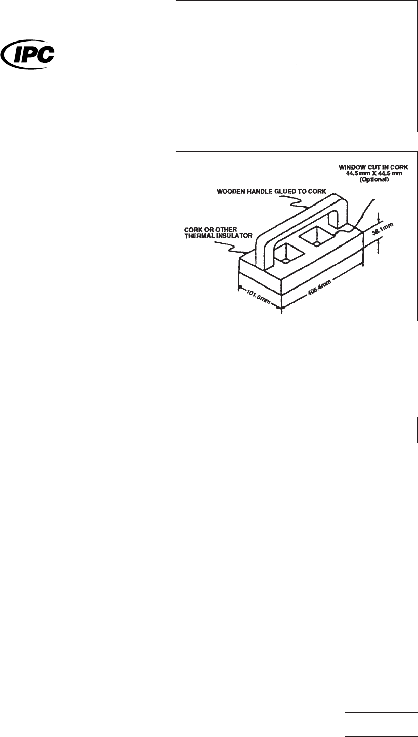
Solder
float test fixture as per Figure 1.
4.5
Sn60,
Sn62, or Sn63 solder conforming to J-STD-004.
5
Procedure
5.1
Prepare
two specimens, clean the copper foil, then pre-
condition the test specimen in an air circulating oven main-
tained at 135°C ± 10°C for one hour. Specimens may then be
held in a room temperature desiccator.
5.2
Remove
the specimens from the conditioning chamber.
5.3 Attach
the specimens to the solder float test fixture with
a thumb tack or other low mass holding device (Figure 1) prior
to floating the sample. Float the specimen, foil side down, on
the surface of the molten solder, maintained at the tempera-
ture specified in Table 1, for 10 seconds.
T
able 1 Solder Float Temperatures
Method
A 260°C ± 5°C
Method B 288°C ± 5°C
5.4
Float
the specimen on the surface, then remove the
specimens and tap the edges to remove excess solder.
5.5
Evaluation
Thoroughly
clean each specimen and visu-
ally examine for blistering, delamination or wrinkling. For bare
dielectric films, examine for blistering, shrinkage, distortion or
melting.
6 Notes
6.1
For
materials that absorb moisture, the preconditioning
in this method is required to remove absorbed moisture from
the materials. Absorbed moisture can volatilize and cause
delamination and blistering because of the rapid temperature
rise experienced in the solder bath. Drying may not be
required for materials with low moisture absorption character-
istics.
IPC-1412-1
Figure
1 Solder float test fixture
The
Institute for Interconnecting and Packaging Electronic Circuits
2215 Sanders Road • Northbrook, IL 60062-6135
IPC-TM-650
TEST
METHODS MANUAL
Number
2.4.13
Subject
Solder
Float Resistance Flexible Printed Wiring
Materials
Date
5/98
Revision
F
Originating Task Group
Flex Peel Strength Test Methods Task
Group (D-13A)
Material
in this Test Methods Manual was voluntarily established by Technical Committees of the IPC. This material is advisory only
and its use or adaptation is entirely voluntary. IPC disclaims all liability of any kind as to the use, application, or adaptation of this
material. Users are also wholly responsible for protecting themselves against all claims or liabilities for patent infringement.
Equipment referenced is for the convenience of the user and does not imply endorsement by the IPC.
P
age1of1
电子技术应用 www.ChinaAET.com

1.0
Scope
This
test method is designed to determine the
thermal integrity of unclad or metallic clad laminates using
short-term solder exposure.
2.0
Applicable Documents
IPC-TM-650 Test Methods Manual
Method
2.1.1, Microsectioning
MIL-F-14256
Flux,
Soldering, Liquid (Rosin Base)
3.0
Test Specimens
3.1 Size and Configuration
Unless
otherwise specified,
specimens shall be 50.8 mm x 50.8 mm ± 0.75 mm [2.00 x
2.00 in ± 0.30 in] by the thickness of the laminate. Metallic
clad laminate shall include specimens which are completely
clad and fully etched.
3.2
Quantity and Sampling
Unless
otherwise specified,
for each clad side and for each test condition, three speci-
mens shall be used for qualification testing and two speci-
mens for lot acceptance testing. Specimens may be cut from
anywhere in the sheet of material except no specimen shall be
taken closer than 25.4 mm [1.0 in] from any edge as lami-
nated.
4.0
Apparatus or Material
4.1 Oven
Air
circulating oven capable of maintaining a tem-
perature of 125 ± 2°C [257 ± 3.6°F].
4.2
Solder Bath
Electrically
heated solder pot; thermostati-
cally controlled; containing at least 1.0 kilograms of solder;
and capable of maintaining the specified temperature. Unless
otherwise specified, the temperature shall be 288 ± 5.5°C
[550 ± 10°F]. Type Sn60 or Sn63 shall be used.
4.3
Temperature Indicator
Thermocouple
or other device
capable of measuring the solder temperature at a depth of
25.4 mm [1 in] below the surface and capable of measuring
to within ± 2°C [3.6°F] at the solder temperature specified.
4.4
Desiccator
A
desiccation chamber capable of main-
taining an atmosphere less than 30% RH at 23°C [73.4°F].
4.5
Optical Magnification
4.5.1 Microscope
Range
100 to 200 X (for referee testing
only).
4.5.2
Magnifier
Magnifying
loupe, or equivalent, capable
of magnification of 4X to 10X.
4.6
Timer
Stop
watch, or equivalent, capable of measuring
to within 0.2 seconds.
4.7
Water White Rosin Flux
Type
R per MIL-F-14256.
4.8
Cutting Apparatus
Diamond
saw, shear or other
device capable of cutting to the specified size without exces-
sive damage or stress on the material.
4.9
Etching System
Etching
system capable of complete
removal of metallic cladding.
4.10
Flux Cleaning Solvent
Isopropyl
alcohol, flux thinner,
or equivalent.
5.0
Procedure
Specimens
shall be tested in accordance
with the following procedure.
5.1
Specimen Preparation
5.1.1 Etching
One-half
of the metallic clad laminate sam-
pling shall be completely etched in accordance with standard
industry practices.
5.1.2
Cutting
The
specimens shall be cut to size from the
unetched and etched samples by suitable means. The edges
shall be cleaned and smoothed by light sanding.
5.1.3
Conditioning
For
referee or qualification purposes,
specimens shall be placed in an air-circulating oven main-
tained at 125°±2°C [257 ± 3.6°F] for 4 to 6 hours. After
removal from the oven, place specimens in a desiccator and
allow to cool to room temperature.
5.2
Measurement
The
Institute for Interconnecting and Packaging Electronic Circuits
2215 Sanders Road • Northbrook, IL 60062-6135
IPC-TM-650
TEST
METHODS MANUAL
Number
2.4.13.1
Subject
Thermal
Stress of Laminates
Date
12/94
Revision
Originating Task Group
MIL-P-13949 Test Methods Task Group (7-11b)
Material
in this Test Methods Manual was voluntarily established by Technical Committees of the IPC. This material is advisory only
and its use or adaptation is entirely voluntary. IPC disclaims all liability of any kind as to the use, application, or adaptation of this
material. Users are also wholly responsible for protecting themselves against all claims or liabilities for patent infringement.
Equipment referenced is for the convenience of the user and does not imply endorsement by the IPC.
P
age1of2
电子技术应用 www.ChinaAET.com

5.2.1
Fluxing
Immediately
after removal from the desicca-
tor, metal surfaces shall be cleaned by light abrasion, or other
suitable methods. Flux with rosin flux conforming to type R,
MIL- F-14256. Let drain in a vertical position.
5.2.2
Stressing
Within
10 minutes of removal from desic-
cator, float the specimen for 10 + 1, –0 seconds on the sur-
face of a solder bath maintained at the specified temperature,
measured at a depth of 25.4 mm [1.0 in] below the surface.
The specimens shall be kept in intimate contact with the sol-
der surface and agitated by gentle downward pressure using
tongs or equivalent.
Note:
Very
thin laminates, typically under 0.5 mm [0.020 in]
thick, are prone to bowing or curling upon contact with solder.
The following handling instructions apply:
a. For etched specimens, mount each specimen using
staples to a piece of corrugated board (‘‘cardboard’’)
approximately 75 x 75 mm [3.0 x 3.0 in].
b. For unetched single-clad specimens, mount each speci-
men to a 75 x 75 mm [3.0 x 3.0 in] piece of corrugated
board (‘‘cardboard’’) by slipping two opposite edges into
slits cut parallel and 38.1 mm [1.5 in] apart in the card-
board.
c. Unetched double-clad specimens including those of
unequal cladding thicknesses, do not require mounting.
5.2.3
The
specimens shall be removed from the bath and
allowed to cool to room temperature. Mounted specimens
may be removed from the supporting cardboard. Clean the
flux from the specimens using appropriate solvent.
5.3
Evaluation
5.3.1 Etched or Unclad Specimens
Examine
the speci-
mens by normal or corrected 20/20 vision, using backlighting
if necessary. Record the presence of charring, surface con-
tamination, loss of surface resin, resin softening, delamination,
blistering, weave exposure, propagation of imperfections,
measling, crazing, or voids.
Determine the number and dimension of any voids using 4X
minimum magnification; for referee purposes, 10X magnifica-
tion shall be used.
5.3.2
Clad Specimens
The
specimen shall be examined
for any evidence of blistering, delamination or other damage.
During the solder exposure, any apparent event that is evi-
dence of damage, such as the specimen exhibiting a ‘‘bump’’
felt through the tongs, shall be recorded as a sign of possible
delamination.
5.3.3
For
referee purposes, the etched or unetched speci-
mens shall then be microsectioned in accordance with IPC-
TM-650, Method 2.1.1 (except there are no plated-through
holes). The microsections shall be examined for degradation
(see 5.6.1) at a magnification of 100X and referee inspection
at 200X.
5.4
Report
Any
observed degradation to the unetched or
etched or unclad specimens shall be reported. The number
and location of voids shall be reported for each specimen.
Results of referee microsection examination will take prece-
dence over visual examination.
6.0 Note
Automatic
(gang mounting) microsectioning tech-
niques may be used.
6.1
Desiccator Conditions
The
Test Methods Task Group
determined that a great majority of test laboratories are unable
to consistently hold the Relative Humidity in a desiccator to
less than 20%. Based on data from participating company lab
management, the lowest practically feasible RH for use with
the affected IPC Test Methods is 30% maximum.
IPC-TM-650
Number
2.4.13.1
Subject
Thermal
Stress of Laminates
Date
12/94
Revision
P
age2of2
电子技术应用 www.ChinaAET.com