IPC-TM-650 EN 2022 试验方法.pdf - 第813页
5.2 Evaluation 5.2.1 Record and report resistance vs. number of rocking cycles. 6 Notes 6.1 Keithley Model 503 Milliohmmeter may be purchased from: KEITHLEY INSTRUMENTS, INC. 28775 Aurora Road Cleveland, Ohio 44139 (216)…
1 Scope The purpose of this test method is to determine
the susceptibility of non-noble metal contact interfaces to the
phenomena of fretting corrosion. Fretting corrosion is an
accelerated oxidation of contact surfaces brought about by
small amplitude cyclic relative motions between mating con-
tacts. In this test, a driving motion is imposed, which tends to
cause relative motion at the contact surfaces. From contact
resistance measurements, one determines whether the result-
ing contact motion, if any, generates significant or detrimental
films in the contact interface.
2 Applicable Documents None
3 Test Specimens
3.1
Any pre-production or production connectors
4 Equipment/Apparatus
4.1
Clamping fixture for test connector(s) and test boards to
mate with test connectors or, in the case of post receptacles,
postheaders
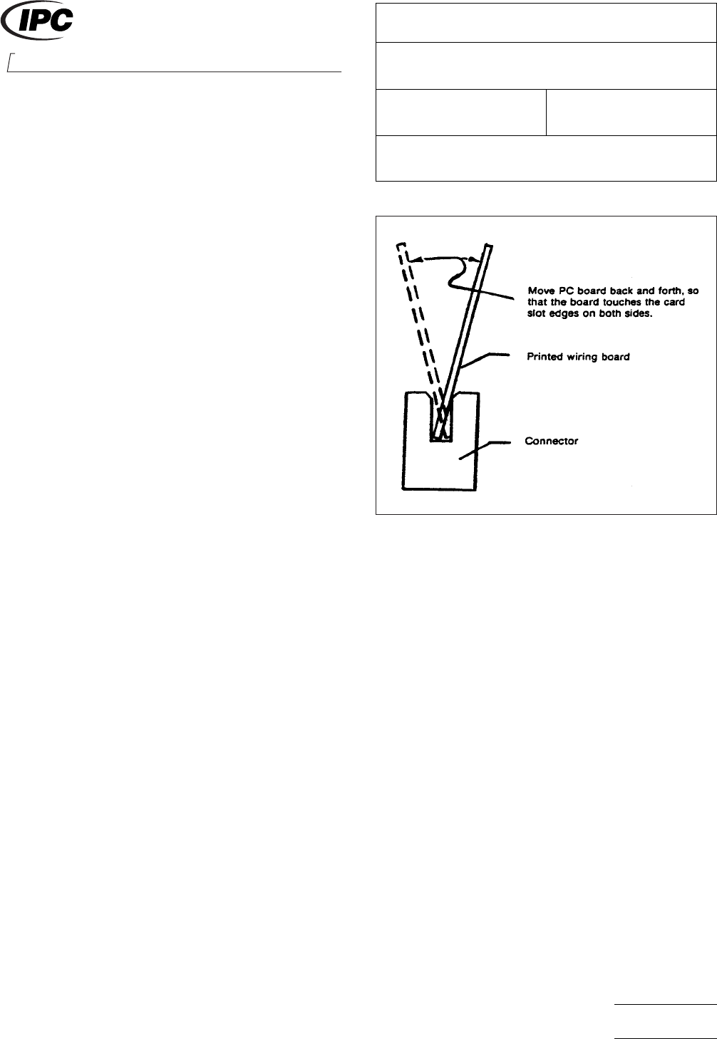
4.2 A motorized cam, crank, or other mechanism, with
appropriate linkage, must be provided to physically attach to
the movable connector, test board, or post and rock this half
back and forth as illustrated in Figure 1. The rocking motion
shall be approximately 10 cycles per minute, but no faster
than 30 cycles per minute.
4.3 The mechanism must be adjustable so as to restrict the
amplitude of motion to one, which, in the case of a PCB sys-
tem, just lets the board touch the card slot in the connector
on each side.
4.4 A counter to record the number of rocking cycles should
be provided.
4.5 A means of measuring contact resistance must be pro-
vided. Dry circuit measuring conditions are to be maintained,
with open-circuit voltages of 50mv or less and test currents of
100 ma or less. A Keithley Model 503 milliohmmeter or its
equivalent may be used.
5 Procedure
5.1 Test
5.1.1
Contacts are to be assembled in their housings as in
normal intended usage.
5.1.2 New test connectors, boards, or posts are to be used
in each test.
5.1.3 Measure and record initial resistance after inserting
test connector(s), board(s), or post(s).
5.1.4 Attach and adjust rocking mechanism, then begin
rocking cycles.
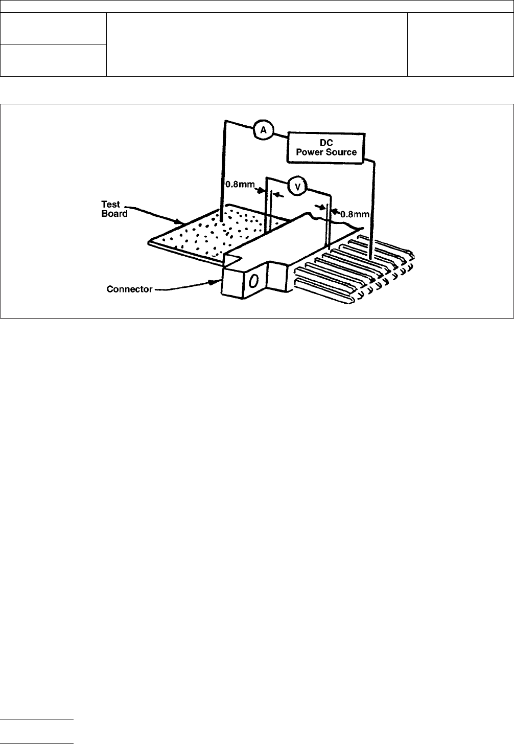
5.1.5 Stop the rocking motion and measure contact resis-
tance after 10, 20, 50, 100, 200, 300, 400, and 500 cycles.
Individual contacts are to be measured separately (see Figure
2).
Note: A millohmmeter having separate current and voltage
leads may be used instead, with leads positioned as shown in
Figure 2.
IPC-3-16-1
Figure 1 Fretting Motion to be Applied to PCB
Connectors
2215 Sanders Road
Northbrook, IL 60062-6135
IPC-TM-650
TEST METHODS MANUAL
Number
3.16
Subject
Fretting Corrosion, Connectors
Date
2/78
Revision
Originating Task Group
Material in this Test Methods Manual was voluntarily established by Technical Committees of the IPC. This material is advisory only
and its use or adaptation is entirely voluntary. IPC disclaims all liability of any kind as to the use, application, or adaptation of this
material. Users are also wholly responsible for protecting themselves against all claims or liabilities for patent infringement.
Equipment referenced is for the convenience of the user and does not imply endorsement by the IPC.
Page1of2
ASSOCIATION CONNECTING
ELECTRONICS INDUSTRIES
5.2 Evaluation
5.2.1
Record and report resistance vs. number of rocking
cycles.
6 Notes
6.1
Keithley Model 503 Milliohmmeter may be purchased
from:
KEITHLEY INSTRUMENTS, INC.
28775 Aurora Road
Cleveland, Ohio 44139
(216) 248-0400
IPC-3-16-2
Figure 2 Method of Making Contact Resistance Measurements
IPC-TM-650
Number
3.16
Subject
Fretting Corrosion, Connectors
Date
2/78
Revision
Page2of2

1 Scope This test method is used to determine the effects
of long term operation of components in atmospheres con-
taining industrial gaseous pollutants. It consists of exposure to
a flowing-gas humid atmosphere containing SO
2
,H
2
S, and
HO
2
in concentrations of 200 parts per billion (ppb). This cor-
responds to a worst-case polluted atmosphere, and is an
accelerated exposure to normal, average pollutant level atmo-
sphere. An acceleration factor of 30-40 is associated with this
test.
1.2 To further simulate and accelerate conditions obtained
in operating environments, the test also involves temperature
and humidity cycling, so as to cause breathing and moisture
condensation on the test samples.
2 Applicable Documents None
3 Test Specimen
3.1
Any pre-production or production samples wired and
mated as intended for actual use
4 Apparatus
4.1
Test chamber and its associated control equipment
capable of producing and maintaining the conditions of 4.1.1
and 4.1.2
4.1.1 Capable of cycling the temperature between 68°C
and 26°C with the following schedule:
Eight hours at 68°C
One hour transition to 26°C
Two hours at 26°C
One hour transition to 68°C
These 12-hour cycles are to be repeated continuously for the
duration of time specified for the exposure.
4.1.2 Capable of maintaining 80% RH ± 5% RH during the
68°C dwell time. Uncontrolled during temperature transitions
so as to allow condensation on the samples.
4.2 Gaseous Atmospheric Pollutants Concentrations of
200 ppb in normal air (N
2
- 20% O
2
) of the following pollutants
shall be maintained in the exposure chamber at all times:
H
2
S (200 ppb)
SO
2
(200 ppb)
NO
2
(200 ppb)
A convenient and satisfactory way of producing this environ-
ment is the ‘‘Battelle Flowing Gas System.’’ In this system, the
pollutant concentrations are maintained through the use of
permeation tubes, which are small Teflon tubing sections,
about 2 cm long, sealed at both ends, and containing the pol-
lutant of interest as a liquid at room temperature. These per-
meation tubes are placed in the main air stream, which feeds
the exposure chamber, and the concentrations of the pollut-
ants are determined by the diffusion rates of the gas out of the
permeation tubes. At a constant flow rate and temperature of
the main air stream, the concentration of pollutants will be
constant. Periodic weighing of the permeation tubes may do
pollutant gas ‘‘analysis.’’
The flow rate of the main air stream is such that the exposure
chamber volume is exchanged approximately every 30 min-
utes.
5 Procedure
5.1
Wire and mate the test specimen as in normal intended
operation during exposure in this test.
5.2 The duration of this test is generally calculated from the
expected service lifetime of the product.
5.3 The actual duration of this exposure is to be determined
between vendor and user and/or is a part of the applicable
product specification. A 60-day exposure in this test corre-
sponds to approximately six years of exposure in normal
industrial environments.
6 Notes
6.1 Reference
Abbott, W. H., Effects of Industrial Air Pol-
lutants on Electrical Contact Materials, Holm Seminar on Elec-
tric Contact Phenomena, November 1973.
2215 Sanders Road
Northbrook, IL 60062-6135
IPC-TM-650
TEST METHODS MANUAL
Number
3.17
Subject
Industrial Gas Test (Battelle Method), Connectors
Date
2/78
Revision
Originating Task Group
Material in this Test Methods Manual was voluntarily established by Technical Committees of the IPC. This material is advisory only
and its use or adaptation is entirely voluntary. IPC disclaims all liability of any kind as to the use, application, or adaptation of this
material. Users are also wholly responsible for protecting themselves against all claims or liabilities for patent infringement.
Equipment referenced is for the convenience of the user and does not imply endorsement by the IPC.
Page1of1
ASSOCIATION CONNECTING
ELECTRONICS INDUSTRIES