IPC-TM-650 EN 2022 试验方法.pdf - 第601页
5.5 Calculations 5.5.1 The volume resistivity shall be calculated as follows: r= R A T Where: r = Volume resistivity in megohm-centimeters R = Measured volume resistance in megohms A = Effective area of the guarded elect…
5.3.4
All
electrical measurements shall be made using 500
volts direct current. The voltage shall be applied to the speci-
men for 60 +5, -0 seconds prior to taking the actual reading,
for stabilization purposes.
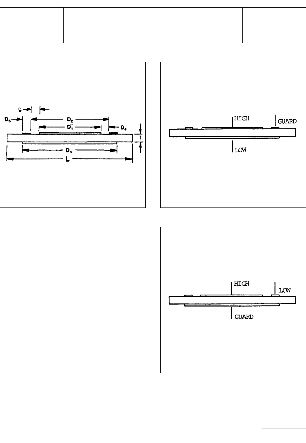
5.3.5
Measure
the volume resistance by connecting the
resistance measuring device to the specimen electrodes
through the fixture system as described in 4.5 in accordance
with Figure 2.
5.3.6
Measure
the surface resistance by interchanging the
test cables connecting the solid back electrode and the outer
ring to the instrument for the arrangement shown in Figure 3.
5.4
Specimen Thickness
Each
specimen shall be mea-
sured for its thickness without cladding. Specimens for each
test condition shall have their thickness readings averaged.
Figure
1 Test pattern dimensions (See table)
Figure
2
Figure
3
IPC-TM-650
Number
2.5.17.1
Subject
Volume
and Surface Resistivity of Dielectric Materials
Date
12/94
Revision
A
P
age3of4
电子技术应用 www.ChinaAET.com

5.5
Calculations
5.5.1
The
volume resistivity shall be calculated as follows:
r=RA
T
Where:
r = Volume resistivity in megohm-centimeters
R = Measured volume resistance in megohms
A = Effective area of the guarded electrode in square centi-
meters
T = Average thickness of specimen in centimeters
T = (t) x 2.54 [see 5.2.1]
t = Average thickness (t) in inches (from 5.4)
Note:
The
value of A may be obtained from the Dimension
Table.
5.5.2
The
surface resistivity shall be calculated as follows:
r
1
=R
1
P
D4
Where:
r
1
=
Surface resistivity in megohms
R
1
=
Measured surface resistance in megohms
P = Effective perimeter of the guarded electrode in centime-
ters
D4 = Width of the test gap in centimeters
Note:
The
ratio of P/D4 for the electrode configuration being
used may be obtained from the Dimension Table included in
Figure 1.
5.6
Reporting
5.6.1
The
volume resistivity of each specimen and the aver-
age shall be reported. Each condition tested shall be reported
separately.
5.6.2 The surface resistivity of each specimen and the aver-
age shall be reported. Each condition shall be reported sepa-
rately.
5.6.2.1 The
surface resistance is the direct reading of the
megohmeter scale and should be recorded in megohms.
6.0
Notes
6.1
For
additional information see ASTM-D-257, D-C Resis-
tance or Conductance of Insulating Materials.
6.2
The
system of electrical connections to the specimens
may benefit from a coaxial cable set-up designed to shield the
measurement of volume or surface resistances from electrical
interference.
6.3
Performance Specifications
The
following informa-
tion should be reviewed within the applicable performance
specification or product procurement document:
a. Specimen size, quantity, and configuration, if other than
that specified in 3.0.
b. Conditioning parameters, such as temperature for Elevated
Temperatures.
c. Any other changes to the specified procedures in this
method.
IPC-TM-650
Number
2.5.17.1
Subject
Volume
and Surface Resistivity of Dielectric Materials
Date
12/94
Revision
A
P
age4of4
电子技术应用 www.ChinaAET.com
1
Scope
This
test method covers the two-wire resistance
test for the determination of the volume resistivity of polymer-
based conductive pastes and other conductive materials used
in HDI. This test is valid for conductive materials with volume
resistivity on the order of 10
-5
Ω-cm
or higher. For measuring
resistivity on highly conductive materials or any material that
cannot be patterned into a circuit pattern, a four-wire (Kelvin
Probe) test method, such as IPC-TM-650, Method 2.5.14, is
recommended.
1.1
Definition
Volume
resistivity is a material property that
can be utilized to calculate the resistance in a circuit design.
For materials with high resistivity, a two-wire resistance test
may be used to measure the volume resistivity.
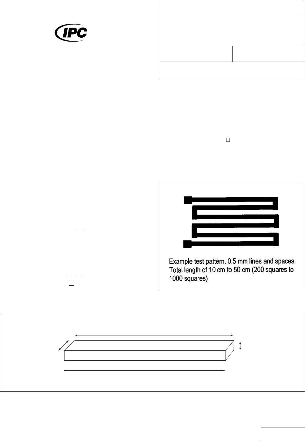
The resistance in any sample (R in units of Ω) is related to the
dimensions of the test circuit and the volume resistivity (ρ)
inherent in the material (see Figure 1).
R =ρ
(
L
tW
)
L,
W, and t are the length, width, and thickness respectively
of the test circuit (in cm). The quantity L/W is called a square,
([). The volume resistivity can then be expressed as:
ρ=
Rt
(
L
W
)
=
Rt
[
with
units of ohms-cm (Ω-cm).
2
Applicable Documents
IPC-TM-650
Test
Methods Manual
2.5.14 Resistivity of Copper Foil
3
Test Specimen
The
test specimen is a 0.5 mm wide
serpentine circuit pattern (see Figure 2) with a length of
between 200 [ and 1000
(length
equal to 200 to 1000
times the width) prepared by screen printing or other meth-
ods. Specimens may be prepared by other methods, as long
as they have measurable dimensions. If materials cannot be
prepared in a circuit pattern, see 6.2.
IPC-2-5-17-2-1
Figure
1 Resistivity Diagram
Conductor
Length = L
Current Flo
w
Width = W
Thickness = t
IPC-25172-2
Figure
2 Serpentine Pattern
The
Institute for Interconnecting and Packaging Electronic Circuits
2215 Sanders Road • Northbrook, IL 60062
IPC-TM-650
TEST
METHODS MANUAL
Number
2.5.17.2
Subject
Volume
Resistivity of Conductive Materials Used in
High Density Interconnection (HDI) and Microvias,
Two-Wire Method
Date
11/98
Revision
Originating Task Group
HDI Test Methods Task Group (D-42a)
Material
in this Test Methods Manual was voluntarily established by Technical Committees of the IPC. This material is advisory only
and its use or adaptation is entirely voluntary. IPC disclaims all liability of any kind as to the use, application, or adaptation of this
material. Users are also wholly responsible for protecting themselves against all claims or liabilities for patent infringement.
Equipment referenced is for the convenience of the user and does not imply endorsement by the IPC.
P
age1of3
电子技术应用 www.ChinaAET.com