IPC-TM-650 EN 2022 试验方法.pdf - 第802页
IPC-3-12-a Figure 1 Right Angle Connector Fixture (Suggested) IPC-3-12-2 Figure 2 Parallel Connector Fixture (Suggested) IPC-TM-650 Number 3.12 Subject Vibration, Connectors Date 7/75 Revision A P a g e2o f6

1.0 Scope
1.1
To determine the effect on the connector of the stresses
produced by mechanical vibration within the predominant fre-
quency ranges and of amplitudes that may be encountered
during field service; two input vibration types are provided:
Sinusoidal — Used to determine critical frequencies, modes
of vibration, and other data necessary for planning protective
steps against the effects of undue vibration. The simple har-
monic motion provided by this method is not representative of
most vibration encountered during field service.
Random — Used to provide a closer approximation to the
complex, non-periodic vibration encountered during field ser-
vice.
2.0 Reference Documents
2.1
Information in this section is intended to parallel the test
method described in EIA-RS-364/TP-28.
3.0 Test Specimen
3.1
A connector (plug and receptacle) complete with appli-
cable guide, keying, and engaging hardware or a card-edge
receptacle and mating nominal-thickness printed circuit
board.
3.2 Mounting and Termination
3.2.1 Right Angle, Two-Piece Connector
The receptacle
shall be mounted and terminated normally during this test;
receptacles designed for mounting on non-rigid bases (e.g.,
motherboards, metal-plate back panels, etc.) shall be
mounted on the smallest section of such a base that will
accommodate the test specimen. The plug shall be termi-
nated normally during this test and shall be mounted on a
nominal-thickness printed circuit board extending the full
width of the plug; the board shall extend a minimum of four
inches from the receptacle when the connector is mated.
3.2.2 Card-Edge Receptacle The receptacle shall be
mounted and terminated normally during this test (see 3.2.1 ).
The mating printed circuit board shall extend the full width of
the receptacle and shall extend a minimum of four inches from
the receptacle when mated.
3.2.3 Parallel, Two-Piece Connector The receptacle and
plug shall be terminated normally during this test; both com-
ponents shall be mounted on nominal-thickness printed circuit
boards extending the full width of each. The printed circuit
boards shall extend a minimum of four inches from each com-
ponent when the connector is mated.
3.3 Fixturing
3.3.1 Right Angle Connector
The test specimen shall be
held in an adequate resonant free fixture. (Figure 1, Reference
example.)
3.3.2 Parallel Connector The test specimen shall be held
in an adequate resonant free fixture. (Figure 2, Reference
example.)
3.4 The connector shall be wired (or printed circuit boards
designed) such that a continuous electrical circuit (comprising
all contacts in series) is formed when the plug (or board) and
receptacle are mated.
4.0 Apparatus
4.1
An electrodynamics vibration system and associated
instrumentation capable of producing the vibration indicated in
Table 1 and Figures 3 and 4 as specified in the individual con-
nector specification. The system shall be capable of maintain-
ing the vibratory input within the following tolerances:
Displacement – ± 10%
Acceleration – ± 10%
Power Spectral Density – ± 3.0 DB (50 Hz maximum
filter bandwidth)
Frequency – ± 2%
4.2 A circuit monitor capable of supplying a continuous cur-
rent of 100 milliamperes and of detecting discontinuities in this
current greater than 1 microsecond.
5.0 Procedure
5.1 Calibration
5.1.1
The vibration system shall be set up to provide the
sinusoidal or random vibratory input in accordance with
2215 Sanders Road
Northbrook, IL 60062-6135
IPC-TM-650
TEST METHODS MANUAL
Number
3.12
Subject
Vibration, Connectors
Date
7/75
Revision
A
Originating Task Group
N/A
Material in this Test Methods Manual was voluntarily established by Technical Committees of the IPC. This material is advisory only
and its use or adaptation is entirely voluntary. IPC disclaims all liability of any kind as to the use, application, or adaptation of this
material. Users are also wholly responsible for protecting themselves against all claims or liabilities for patent infringement.
Equipment referenced is for the convenience of the user and does not imply endorsement by the IPC.
Page1of6
ASSOCIATION CONNECTING
ELECTRONICS INDUSTRIES
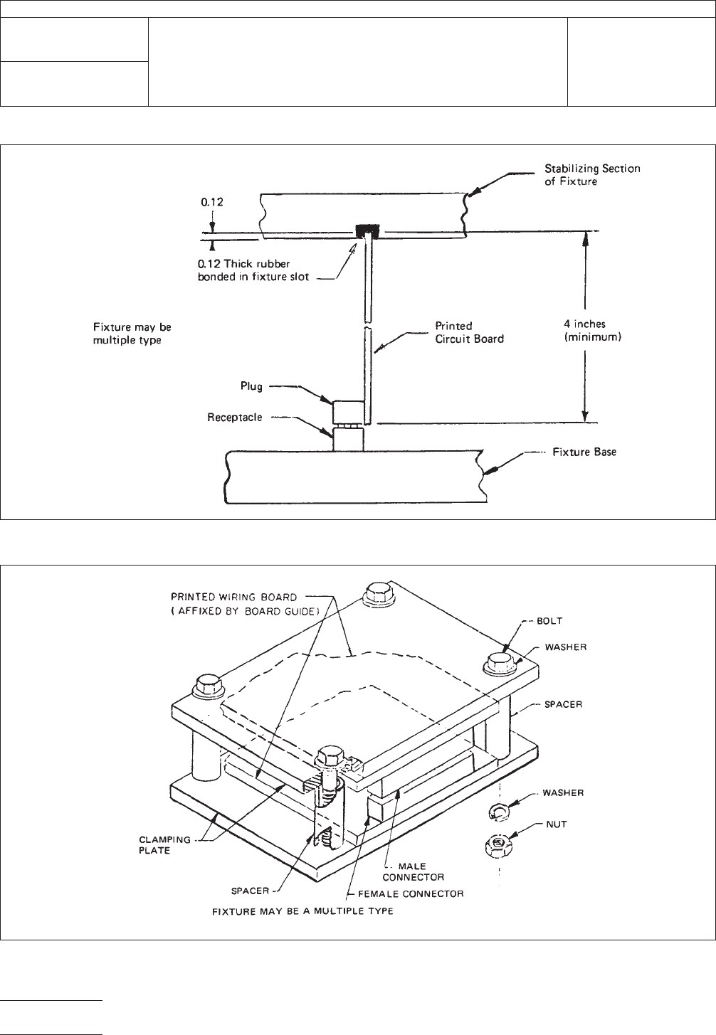
IPC-3-12-a
Figure 1 Right Angle Connector Fixture (Suggested)
IPC-3-12-2
Figure 2 Parallel Connector Fixture (Suggested)
IPC-TM-650
Number
3.12
Subject
Vibration, Connectors
Date
7/75
Revision
A
Page2of6

Table 1 and Figure 3 or 4 as specified in the individual con-
nector specification; if no test is specified, Test Condition D
shall apply.
5.1.2 The fixtured test sample or a suitable dummy load
shall be mounted on the vibration exciter during the calibration
procedure. Any dummy load shall have the mass and center
of gravity as that of the test sample and shall be fixtured in a
similar manner (a reject connector provides an ideal dummy
load).
5.1.3 The control transducer shall be mounted on the test
fixture immediately adjacent to the test specimen or dummy
load. The displacement-acceleration curve of the sinusoidal
input or the equalized random input shall fall within, the speci-
fied tolerances.
5.2 Sinusoidal Vibration Test
5.2.1
The dummy load shall be replaced with the actual test
sample.
5.2.2 The test sample shall be connected to the discontinu-
ity monitor and a minimum current of 100 milliamperes shall
be established in the series circuit comprising all contacts of
the test sample.
5.2.3 The test sample shall be subjected to the sinusoidal
test condition specified in the individual connector specifica-
tion; the following details shall apply:
A. Amplitude — The test sample shall be subject to simple
harmonic motion at an amplitude of 0.06 inch double
amplitude (peak-to-peak displacement) or the maximum
acceleration specified in Table 1, whichever is less.
B. Frequency Range — The vibration frequency shall be var-
ied logarithmically between the approximate limits speci-
fied in Table 1; see 6.2 for alternate method.
C. Range Traverse Time and Duration — The entire fre-
quency range shall be traversed in a time as specified in
Table 1. The traverse (in either direction) shall be per-
formed the indicated number of times along each of three
(3) orthogonal axes for at least the indicated total vibration
period per axis. If the procedure of Test Condition A is
used for the 10 to 55Hz band of Test Conditions B, C or
E, the duration of this portion shall be the same as the
duration for this band using logarithmic cycling at the rate
specified for Test Conditions B, C or E (approximately
1-1/3 hours along each of 3 orthogonal axes).
5.3 Random Vibration Test
5.3.1
The dummy load shall be replaced with the actual test
sample.
5.3.2 The test sample shall be connected to the discontinu-
ity monitor and a minimum current of 100 milliamperes shall
be established in the series circuit comprising all contacts of
the test sample.
Table 1 Test Conditions
Test
Condition
Peak Acceleration
(Gravity Units)
Frequency
Range
Approx. Traverse
Time
1
Traverses
Per Axis
Duration
Per Axis
A 10 5 to 55 Hz 0.5 min. 240 2 hrs.
B 10 10 to 500 Hz 7.5 min. 24 3 hrs
C 15 10 to 2000 Hz 10 min. 24 4 hrs.
D
2/3
10 55 to 2000 Hz 40 min. 1 40 min.
E 20 10 to 2000 Hz 10 min. 24 4 hrs.
F 10.9
4
10 to 2000 Hz N/A N/A 15 min.
1
Traverse time is that time to go from the lower frequency to the higher frequency, or vice versa.
2
Test Condition D shall be preceded by vibration tests per Test Condition A.
3
Test Condition D is intended to isolate resonant frequencies. If resonance is detected, the test sample shall be vibrated at each critical resonant frequency
for 5 minutes; critical resonance is defined as a point on the test sample observed to have a maximum amplitude (or acceleration) more than twice that of
the controlled input.
4
Overall root-mean-square (RMS) acceleration.
IPC-TM-650
Number
3.12
Subject
Vibration, Connectors
Date
7/75
Revision
A
Page3of6