IPC-TM-650 EN 2022 试验方法.pdf - 第426页
IPC-2541-1 Figure 1 T est Pattern IPC-2541-2 Figure 2 T est Circuit IPC-TM-650 Number 2.5.4.1 Subject Conductor Temperature Rise Due to Current Changes in Conductors Date 8/97 Revision A P a g e3o f3 电子技术应用 www.ChinaAET.…

this
resistor is to provide a reference for measuring the cur-
rent. Its value should be of the same order of magnitude as
that of the conductor under test to minimize scale changes in
measurements.
5.2.5
Measurements
at specific currents are to be made
after thermal stabilization. The elapsed time between these
two measurements should be as small as possible.
5.2.6
Measure
the voltage drops across the external series
resistor and the test section of the current carrying conductor
(R).
5.3
Evaluation
5.3.1
The
value of the temperature coefficient of resistance
(α) shall have been determined and identified. Temperature
coefficients for various electrical conductor materials are given
in American Society for Testing Materials-B193-65.
5.3.2
When
the temperature coefficient of resistance of the
conductor is unknown, it may be determined by measuring
the resistance of the conductor at different oven tempera-
tures, and calculated by the formula:
α
t
1
=
R
t
2
–R
t
1
R
t
1
(t
2
–t
1
)
and
adjusted to the desired ambient temperature by:
α
t
=
1
1
α
t
1
+(t–t
1
)
5.3.3
Determine
the cross sectional area of the conductor
under test by use of the formula for volume resistivity.
p
v
=
A
L
R
where p
v
=
volume resistivity in ohm-circular mil/ft
A = cross sectional area in circular mils
L = gage length, used to determine R in feet
R = measured resistance in ohms (R
t
1
,
see
calculations)
A =
p
v
L
R
where p
v
=
11,529 ohm cir mil/ft @ 25°C for 1/2 oz. of
copper
= 10.827 ohm cir mil/ft @ 25°C for 1 oz. and over
L = 0.5 ft. (Fig. 1 - test pattern)
A = Are in cir mils.
A x 0.7854 = Area in square mils
5.4
Calculations
The
temperature rise of a conductor is
determined by measuring the change in resistance of the test
length of conductor and using the relationship.
R
t
= R
t
1
[1 +α
t
1
(t–t
1
)]
R
t
=
Resistance of conductor at the desired current.
R
t
=
Resistance of conductor at reference temperature (t
1
).
α
t
1
=
Temperature coefficient of resistance of conductor at
reference temperature (t
1
).
t
1
= Reference temperature; that ambient temperature at
which R
t1
was
measured.
The following relationship can be derived from the foregoing
using voltage drops:
∆
t
=
1
α
t
1
[
R
t
R
t
1
–1
]
R
t
=
E
R
t
R
S
E
S
t
∆
t
=
1
α
t
1
[
R
R
1
E
S
t
R
S
R
t
1
–1
]
=
1
α
t
1
[
E
R
t
E
S
t
E
S
t
1
E
R
t
1
–1
]
E
R
t
=
Voltage drop across test conductor at the desired cur-
rent.
E
R
t
1
=
Voltage drop across test conductor at the reference
current.
E
S
t
=
Voltage drop across the external series resistor at the
desired current.
E
S
t
1
=
Voltage drop across the external series resistor at the
reference current.
R
s
=
Resistance of external series resistor.
R
t
1
=
Resistance of test conductor at the reference tempera-
ture. Determined by measuring voltage drop with less
than 100 mA current passing through conductor and
determined from
R
t
1
=
E
R
t
1
l
1
where
i
1
=
E
S
t
1
R
S
IPC-TM-650
Number
2.5.4.1
Subject
Conductor
Temperature Rise Due to Current Changes in
Conductors
Date
8/97
Revision
A
P
age2of3
电子技术应用 www.ChinaAET.com
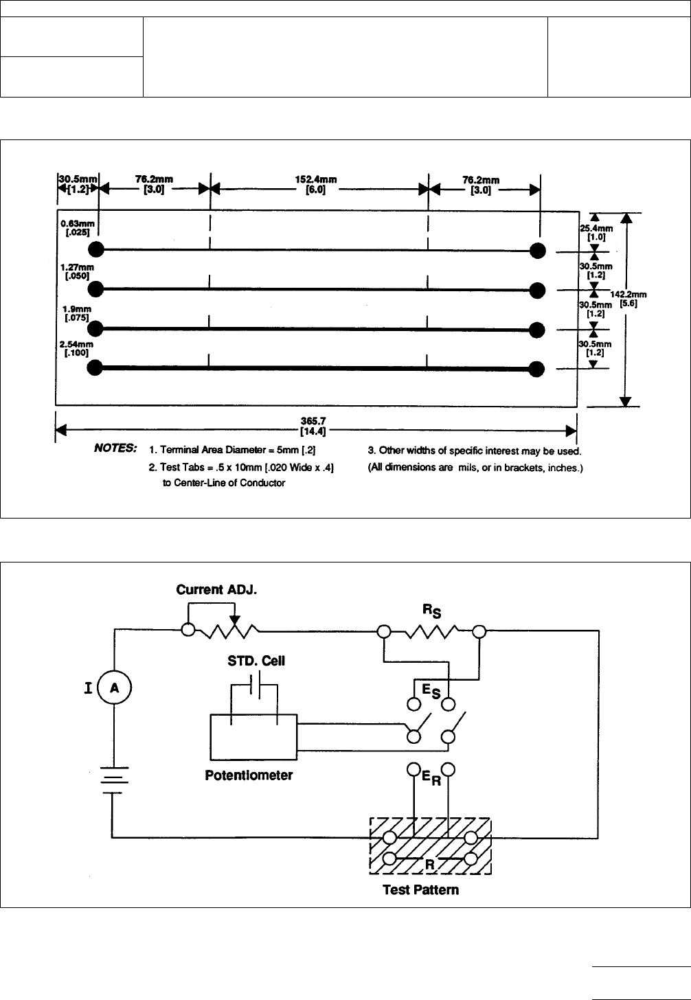
IPC-2541-1
Figure
1 Test Pattern
IPC-2541-2
Figure
2 Test Circuit
IPC-TM-650
Number
2.5.4.1
Subject
Conductor
Temperature Rise Due to Current Changes in
Conductors
Date
8/97
Revision
A
P
age3of3
电子技术应用 www.ChinaAET.com

1.0
Scope
This
test method is to determine the dielectric
constant and dissipation factor of raw printed wiring board
material at 1 MHz.
2.0
Applicable Documents
None
3.0
Test Specimens
Each
specimen shall be 50.8 ± 0.076
mm [2.0 ± 0.003 in] in diameter by thickness of laminate or
substrate material. Remove copper of metal-clad specimens
by etching using standard commercial practices. At least
three specimens are required.
4.0
Equipment/Apparatus
4.1 Meter
A
1 MHz Digital LCR Meter, Hewlett Packard
Mdl 4271A or equivalent.
4.2
Test Fixture
Hewlett
Packard Mdl 16022A test fixture
or equivalent.
4.3
Specimen Holder
A
special specimen holder made as
shown in Figure 1. This holder is designed to be compatible
with the H/P test fixture, Mdl 16022A.
4.0
Procedure
5.1 Preparation
5.1.1
Prepare
the specimens as specified in paragraph 3.0.
5.1.2 Calculate
the effect thickness (inches) =
0.01942 x Mass
Density
Mass
= Measured weight in grams
Density = Grams per cubic cm (as per ASTM-D-792,
Method 1A)
5.1.3
Coat
both sides of specimens with one uniform coat-
ing of silver conductive paint.
5.1.4
Air-dry
the specimens until dry to touch, then oven-dry
at 50°±2°C for 1/2 hour and cool in a desiccator.
5.1.5
Punch
or machine a 25.4 mm [1.0 in] diameter disc
from the 50.8 mm [2.0 in] specimens. (Assure that there is no
carry over of the paint from one side to the other.)
5.1.6 Condition
the 25.4 mm [1.0 in] specimens for a mini-
mum of 40 hours at 23°±5°C at a relative humidity of 50%.
5.2
Testing
5.2.1
Turn
meter on and allow to warm up for 60 minutes
minimum.
5.2.1.1
Set
the controls on the meter as follows:
Function – C-D
Range – Manual
Trigger – Internal
Rate – FCW
Test Signal Level – Low
5.2.1.2
Connect
the cables for the test fixture to the appro-
priate connectors.
5.2.2
Plug
the special specimen holder into the test fixture.
5.2.3
The
digital display on the meter will show the capaci-
tance value and the dissipation factor of the unknown dielec-
tric specimen.
5.3
Calculation
5.3.1 Dielectric Constant
The
dielectric constant shall be
determined by using the following formula:
K =
Ct
0.225
A
K = Dielectric constant
C = Capacitance reading from Mdl 4271A Meter
A = Area of a 1-inch disc (square inches)
t = Effective thickness (inches)
The
Institute for Interconnecting and Packaging Electronic Circuits
2215 Sanders Road • Northbrook, IL 60062
IPC-TM-650
TEST
METHODS MANUAL
Number
2.5.5.2
Subject
Dielectric
Constant and Dissipation Factor of
Printed Wiring Board Material—Clip Method
Date
12/87
Revision
A
Originating Task Group
N/A
Material
in this Test Methods Manual was voluntarily established by Technical Committees of the IPC. This material is advisory only
and its use or adaptation is entirely voluntary. IPC disclaims all liability of any kind as to the use, application, or adaptation of this
material. Users are also wholly responsible for protecting themselves against all claims or liabilities for patent infringement.
Equipment referenced is for the convenience of the user and does not imply endorsement by the IPC.
P
age1of2
电子技术应用 www.ChinaAET.com