IPC-TM-650 EN 2022 试验方法.pdf - 第432页
7.1 Report the minimum, maximum and average values of the permittivity (dielectric constant). 7.2 Report the average value of the loss tangent (dissipation factor). 7.3 Report the specimen preconditioning, e.g., C-24/23/…

5.4.2
Record
the capacitance of the air filled cell as C
1
to
the
nearest .01 pf (or nearest .001 pf if the 0-20 pf scale is
used).
5.4.3 Remove the specimen from the humidity controlled
environment.
5.4.4
Insert
the first specimen to be tested with the marked
corner remaining in the upper left and the right side of the test
specimen against one side of the test cell. Note: This will
ensure that subsequent measurements are taken using the
same area of the specimen.
5.4.5
Read
and record the value of capacitance with the
specimen in the cell as C
3
.
5.4.6
Remove
the first specimen and obtain C
3
for
any other
specimens to be measured with same cell spacing.
5.4.7
After
removing the last specimen from the cell, fill the
cell with Dow Corning 200 Fluid using the funnel and a filter to
remove any small particles from the fluid and collect any
excess fluid from the overflow pipe on the cell with the small
beaker.
5.4.8
Allow
a few seconds for the temperature of the cell
and fluid to equilibrate and record the capacitance of the liq-
uid filled cell as C
2
.
Note: If
the capacitance is drifting consistently in one direc-
tion, the fluid is not at equilibrium.
5.4.9
Record
the conductance of the fluid filled as cell G
1
.
Note: The
value obtained will vary somewhat with cell spacing
and humidity but should not exceed 500 microsiemen (200
microsiemen if low loss material, with a loss tangent under
.001 is being tested). Values beyond this are generally indica-
tive of problems with the leads, contamination of the fluid or
bridge error and must be corrected if correct dissipation fac-
tor is to be determined.
5.4.10
Insert
the first specimen in the fluid filled cell exactly
as in the dry reading and record the value of the capacitance
as C
4
and
the value of the conductance as G
2
.
Note: Values
should stabilize within a few seconds after speci-
men insertion. If they do not there is very likely air trapped in
the cell. This is quite common if multiple thin specimens are
used to form one test specimen. If this occurs presoaking the
specimen with fluid before immersion and inserting one ply at
a time should eliminate the problem.
5.4.11
Remove
the first specimen and insert each subse-
quent specimen in the same order as the dry values were
obtained and record the C
4
and
G
2
values
for each.
5.4.12 After
the last specimen is measured and removed
from fluid, check and record the values of the capacitance
and conductance.
Note: If the level of the fluid with the specimen removed does
not cover the electrodes, fill the cell before checking the final
values. This check on C
2
will
be used to verify the amount of
influence that changes in ambient temperature have had on
the values obtained.
6.0
Calculation
6.1
Calculate
the value of the permittivity (dielectric constant)
of each specimen tested using the equation:
DK =
1.00058
C1
S
C1
+
(C3−C1)(C2−C1) C4
(C3−C1) C4 −(C4−C2) C3
D
Round
the value obtained to the nearest .01.
6.2
Calculate
the value of the loss tangent (dissipation fac-
tor) of each specimen tested using the equation:
DF =
G2
6.2832
C4
+
S
DK
* .99942 C1−C4
C4−C2
DS
G2
6.2832
C4
−
G1
6.2832
C2
D
Round
the value to the nearest .0001.
Note: Values should be calculated using a computer and must
not be rounded prematurely.
6.3
If
the value of C
2
changed
during the course of the mea-
surements, use the final values of C
2
and
G
2
,
the value of C
1
,
and
the values on the last specimen for C
3
and
C
4
to
recalcu-
late the DK and Df of the final specimen. If the difference in DK
values is significant, the temperature of the cell must be con-
trolled more precisely during the measurement period.
6.4
Calculate
the average permittivity (dielectric constant) (if
more than one specimen was tested).
6.5
Calculate
the average loss tangent (dissipation factor) (if
more than one specimen was tested).
7.0
Report
IPC-TM-650
Number
2.5.5.3
Subject
Permittivity
(Dielectric Constant) and Loss Tangent (Dissipation
Factor) of Materials (Two Fluid Cell Method)
Date
12/87
Revision
C
P
age3of4
电子技术应用 www.ChinaAET.com
7.1
Report
the minimum, maximum and average values of
the permittivity (dielectric constant).
7.2
Report the average value of the loss tangent (dissipation
factor).
7.3 Report the specimen preconditioning, e.g., C-24/23/50.
7.4 Report
the actual test conditions for temperature and
humidity.
7.5
Report
if the specimen was built up.
7.6
Report
the approximate cell spacing.
7.7
Report
any anomalies in the test or variations from the
prescribed procedures or tolerances.
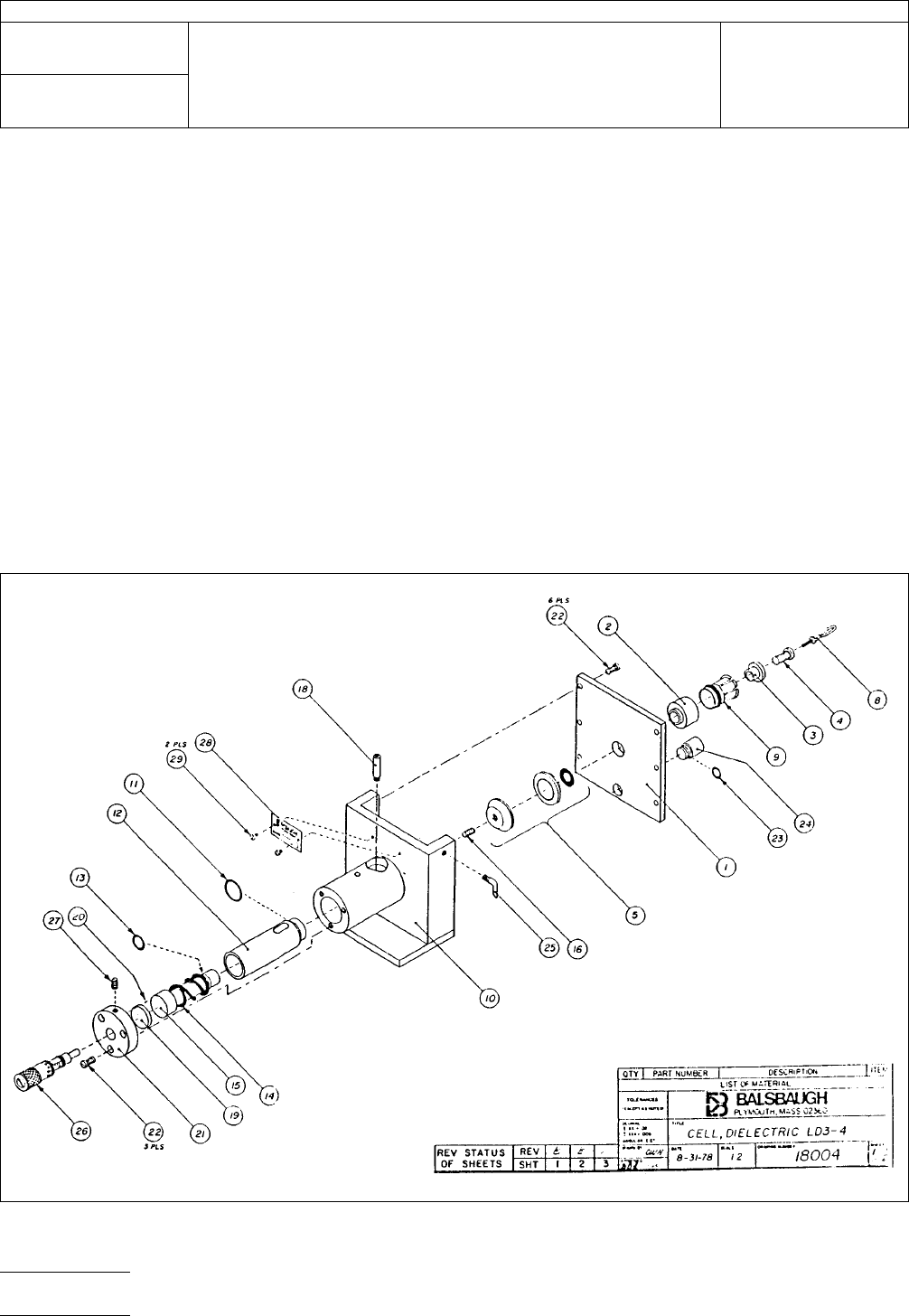
IPC-2553-1
Figure
1
IPC-TM-650
Number
2.5.5.3
Subject
Permittivity
(Dielectric Constant) and Loss Tangent (Dissipation
Factor) of Materials (Two Fluid Cell Method)
Date
12/87
Revision
C
P
age4of4
电子技术应用 www.ChinaAET.com

1.0
Scope
1.1 Summary
This
method is intended for the rapid mea-
surement of the X-band (8.00 to 12.40 GHz) apparent relative
stripline permittivity (see 9.1) and loss tangent of metal clad
substrates. Measurements are made under stripline condi-
tions using a resonant element pattern card, which is sepa-
rated from the ground planes by sheets of the material to be
tested. Further information about this method may be found in
ASTM D3380-75.
1.2
Definitions
Terms
used in this method include:
Complex Relative Permittivity The values for relative per-
mittivity and dissipation factor considered as a complex num-
ber.
Permittivity Dielectric constant (see IPC-T-50) or relative per-
mittivity. The symbol used in this document is ε
r
.K
’orκ’ are
sometimes used.
Relative Permittivity A dimensionless ratio of absolute per-
mittivity of a dielectric to the absolute permittivity of a vacuum.
Loss Tangent Dissipation factor (see IPC-T-50), dielectric
loss tangent. The symbol used in this document is tan δ (see
9.2).
1.3
Limitations
The
following limitations in the method
should be noted. Users are cautioned against assuming the
method yields permittivity and loss tangent values that directly
correspond to applications. The value of the method is for
assuring consistency of product, thus reproducibility of results
in fabricated boards.
1.3.1
The
measured effective permittivity for the resonator
element can differ from that observed in an application.
Where the application is in stripline and the line width to
groundplane spacing is less than that of the resonator ele-
ment in the test, the application will exhibit a greater compo-
nent of the electric field in the X, Y plane. Heterogeneous
dielectric composites are anisotropic to some degree, result-
ing in a higher observed ε
r
for
narrower lines.
Microstrip lines in an application may also differ from the test
in the fraction of substrate electric field component in the X, Y
plane.
Bonded stripline assemblies have air excluded between
boards, thus tend to show greater ε
r
values.
1.3.2
High
degrees of anisotropy of some composites can
result in an increased degree of coupling of the resonant ele-
ment, resulting in a falsely lower Q value. If a correction is not
applied either mathematically as in 7.2.2 or by deviating from
the probe gaps specified for the test pattern, an upward bias
in the calculated loss tangent will result.
1.3.3
The
sensitivity of the method to differences in ε
r
of
specimens
is impaired by the fact that the resonator pattern
card remains as part of the fixture and at the same time con-
stitutes a significant part of the dielectric involved in measure-
ments.
1.3.4
The
method does not lend itself to use of stable ref-
eree specimens of known electric properties traceable to The
National Institute of Standards and Technology (NIST).
2.0
Applicable Documents
2.1 IPC
IPC-T-50
Terms
and Definitions
IPC-MF-150
Metal
foil for Printed Wiring Application
IPC-TM-650
Method
2.3.7.1, Cupric Chloride Etching
IPC-TM-650
Method
2.5.5.3, Permittivity (Dielectric Con-
stant) and Loss Tangent (Dissipation Factor) of Materials (Two
Fluid Cell Method)
ASTM
D3380-75
Standard
Method of Test for Permittivity
(Dielectric Constant) and Dissipation Factor of Plastic-Based
Microwave Circuit Substrates
3.0
Test Specimen
All
metal cladding shall be removed
from the material to be tested by any standard etching pro-
cess, including rinsing and drying; however, IPC-TM-650,
Method 2.3.7.1, shall be used as a referee procedure. The
test specimen shall consist of a set of two sheets (or two
packets of sheets) of a preferred size of at least 51 mm x 69
mm.
3.1 A
smaller size may be used if it has been shown not to
affect results. The minimum vertical dimension must extend
2215
Sanders Road
Northbrook, IL 60062-6135
IPC-TM-650
TEST
METHODS MANUAL
Number
2.5.5.5
Subject
Stripline
Test for Permittivity and Loss Tangent
(Dielectric Constant and Dissipation Factor) at X-Band
Date
3/98
Revision
C
Originating
Task Group
High Speed/High Frequency Test Methods
Subcommittee (D-24)
Material
in this Test Methods Manual was voluntarily established by Technical Committees of the IPC. This material is advisory only
and its use or adaptation is entirely voluntary. IPC disclaims all liability of any kind as to the use, application, or adaptation of this
material. Users are also wholly responsible for protecting themselves against all claims or liabilities for patent infringement.
Equipment referenced is for the convenience of the user and does not imply endorsement by the IPC.
P
age1of25
ASSOCIA
TION CONNECTING
ELECTRONICS INDUSTRIES
电子技术应用 www.ChinaAET.com