IPC-TM-650 EN 2022 试验方法.pdf - 第715页
5.2 Evaluation 5.2.1 During testing, examine the test specimens at 28th, 56th and 84th days. Prior to examining the test specimens, they shall be returned to 25°C [77°F] and 50% relative humid- ity for two hours. Evaluat…
1
Scope
This
test method is to determine the resistance of
the applied conformal coating to reverting to liquid when
exposed to high humidity at a specific temperature and time
condition for each class. This test method is to evaluate the
quality of the coated printed boards under storage conditions
(nonoperating).
2
Applicable Documents
IPC-CC-830
Qualification
and Performance of Electrical Insu-
lating Compound for Printed Board Assemblies
FED-STD-141
Method
4061 (Dry-Through For Varnish, Lac-
quers And Enamels)
3
Test Specimens
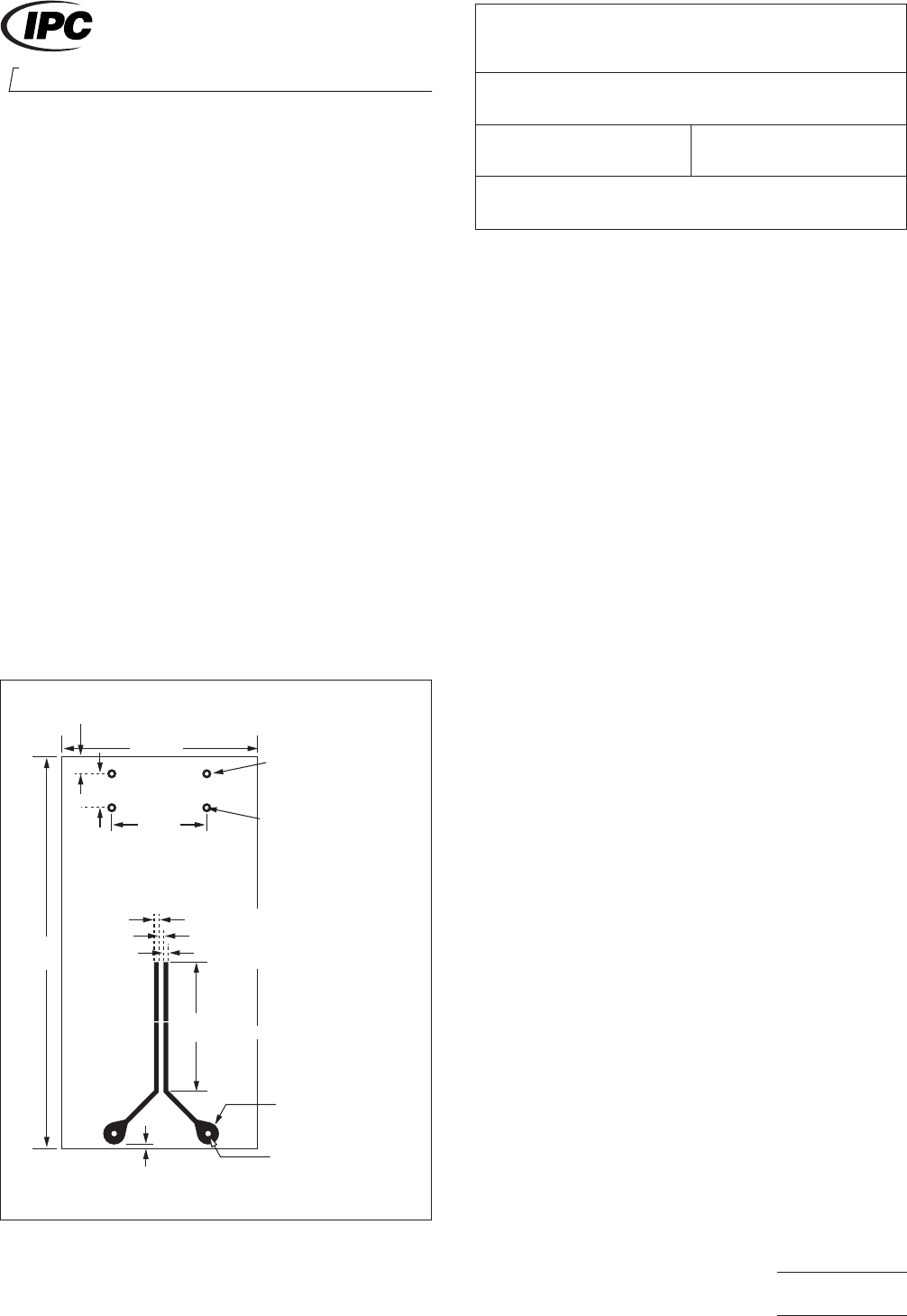
Five
coated ‘‘Y’’ shape patterns (see
Figure 1) containing two resistors, one with marking ink and
one with color code bars, coated with conformal coating per
the coating supplier’s recommendations.
4
Equipment
4.1 Desiccator
At
least 25 cm [9.84 in] in diameter
4.2
Potassium Sulfate
Reagent
grade potassium sulfate
4.3
Cotton Swabs
4.4 Oven
Capable
of maintaining temperature up to 100°C
[212°F].
4.5
Test Chamber
Capable
of maintaining a constant tem-
perature of 85° ± 2°C [185° ± 3.6°F] with 95 ± 4% relative
humidity
4.6
Soldering Iron
If
applicable
4.7
High Temperature Silicone Grease
5.0 Procedures
5.1 Desiccator Method
5.1.1
Prepare
a saturated solution of distilled or deionized
water and potassium sulfate (35 grams per 100 cm
3
)a
ta
temperature of 85° ± 2°C [185° ± 3.6°F]. Pour the solution
into the desiccator just below the ceramic plate. Crystals of
potassium sulfate should remain visible in the saturated solu-
tion during testing.
Note: Relative humidity is not to exceed 98%.
5.1.2 Place
four of the five test specimens on the ceramic
plate in the desiccator so that they are not touching each
other. The fifth specimen is used as a control.
5.1.3
Seal
the desiccator with high temperature silicone
grease and close the desiccator.
5.1.4
Place
the desiccator in the oven maintained at 85° ±
2°C [185° ± 3.6°F].
5.1.5 Allow
the desiccator, containing the test specimens,
to remain in the oven for 120 days.
75 mm
[2.95 in]
4.7 mm
[0.185 in]
38 mm
[1.50 in]
19 mm
[0.748 in]
6.30 mm [0.248 in]
2.3 ± 0.13 mm DIA
[0.091 ± 0.005 in DIA]
Hole 0.75 ± 0.08 mm DIA
[0.029 ± 0.003 in DIA]
0.75 mm [0.029 in MIN]
0.75 mm ± 008 mm [0.029 in ± 0.003 in MIN]
0.75 mm [0.029 in MIN]
3.2 mm
[0.126 in]
25 ± 1.5 mm
[0.984 ± 0.059 in MIN]
3.8 ± 0.13 mm DIA
[0.150 ± 0.005 in DIA]
HOLE 1.3 ± 0.08 mm DIA
[0.051 ± 0.0031 in DIA]
IPC-26111-1
Figure
1 ‘‘Y’’ Shape Pattern
2215
Sanders Road
Northbrook, IL 60062-6135
IPC-TM-650
TEST
METHODS MANUAL
Number
2.6.11.1
(Supersedes
2.6.11B for Conformal Coating Test)
Subject
Hydrolytic Stability - Conformal Coating
Date
07/00
Revision
Originating Task Group
Conformal Coating Task Group (5-33a)
Material
in this Test Methods Manual was voluntarily established by Technical Committees of IPC. This material is advisory only
and its use or adaptation is entirely voluntary. IPC disclaims all liability of any kind as to the use, application, or adaptation of this
material. Users are also wholly responsible for protecting themselves against all claims or liabilities for patent infringement.
Equipment referenced is for the convenience of the user and does not imply endorsement by IPC.
P
age1of2
ASSOCIA
TION CONNECTING
ELECTRONICS INDUSTRIES
电子技术应用 www.ChinaAET.com

5.2
Evaluation
5.2.1
During
testing, examine the test specimens at 28th,
56th and 84th days. Prior to examining the test specimens,
they shall be returned to 25°C [77°F] and 50% relative humid-
ity for two hours. Evaluate the specimens for evidence of
reversion as indicated by softening, chalking, blistering, crack-
ing, tackiness, loss of adhesion or liquefaction. Evaluate also
legibility of the markings on the board and/or the resistors.
5.2.2 After
the 120-day aging period, the panels shall be
returned to 25°C [77°F] and 50% relative humidity and held for
seven days. The specimens shall be evaluated and compared
with the control specimen as per 5.2.1. The specimens shall
also be tested for tackiness in accordance with Method 4061
(Dry-Through For Varnish, Lacquers And Enamels) of FED-
STD-141.
5.3
Chamber Method
5.3.1
Place
four of the five test specimens into the test
chamber, by placing them in a rack or hanging, so that they
do not touch each other. The fifth specimen is held as a con-
trol. Close the chamber door.
5.3.2
Set
the chamber’s parameters at 85° ± 2°C [185° ±
3.6°F] and 95 ± 4% relative humidity. Activate the test cham-
ber and begin testing.
5.3.3
Allow
the specimens to remain in the test chamber for
120 days.
5.4
Evaluation
5.4.1
During
testing, examine the test specimens at 28th,
56th and 84th days. Prior to examining the test specimens,
they shall be returned to 25°C [77°F] and 50% relative humid-
ity for two hours. Evaluate the specimens for evidence of
reversion as indicated by softening, chalking, blistering, crack-
ing, tackiness, loss of adhesion or liquefaction. Evaluate also
legibility of the markings on the board and/or the resistors.
5.4.2
After
the 120-day aging period, the panels shall be
returned to 25°C [77°F] and 50% relative humidity and held for
seven days. The specimens shall be evaluated and compared
with the control specimen as per 5.2.1. The specimens shall
also be tested for tackiness in accordance with Method 4061
(Dry-Through For Varnish, Lacquers And Enamels) of FED-
STD-141.
IPC-TM-650
Number
2.6.11.1
Subject
Hydrolytic
Stability - Conformal Coating
Date
07/00
Revision
P
age2of2
电子技术应用 www.ChinaAET.com
1.0
Scope
This
test method will demonstrate a relative
degree to which uncoated printed wiring boards are suscep-
tible to dendritic growth due to the presence of ionic residues
and condensed moisture. This test method is particularly suit-
able for printed wiring board manufacturing process control.
2.0
Applicable Documents
IPC-TR-476
How
to Avoid Metallic Growth Problems on
Electronic Hardware
MIL-P-551
10
Printed
Wiring Boards
3.0
Test Specimens
Test
pattern is chosen from, but not
restricted to e.g., MIL-P-55110 type ‘‘Y’’ pattern with a pair of
conductors having typically 15-30 mils separation (See Figure
1). A pair of parallel conductors on an uncoated production
printed wiring board, with spacing between conductors of
approximately 15-30 mils is suitable as well.
4.0
Equipment/Apparatus
4.1 Power Supply
A
dc power supply capable of providing
a metered 0-20 V dc, and 100 milliamps current.
4.2
Microscope
50-100
power microscope and means of
providing direct and/or indirect lighting on specimen.
4.3
Miscellaneous Items
DI
water sample (2 oz.) kept in a
plastic bottle, eye dropper, a 1/2 watt-10K ohm current limit-
ing resistor and a stop watch.
5.0
Procedure
5.1 Preparation
5.1.1
Attach
a wire to each of the conductors on the ‘‘Y’’
pattern test board, or to corresponding, parallel conductors
on a production PWB.
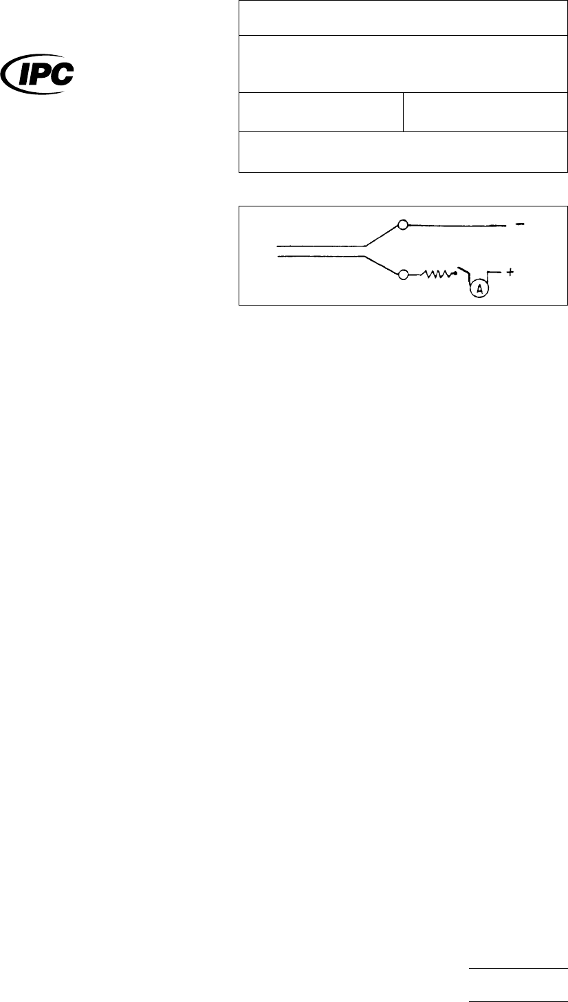
5.1.2
Connect
a 10K resistor in series to the power supply
as shown in Figure 1. The resistor will limit the current to 1.5
milliamp maximum.
5.1.3 Place
the board for viewing on the microscope, so
that the parallel conductors are in view. Provide lighting that
will illuminate the test board on top and/or underneath.
5.1.4
Using
the eye dropper, place a drop of DI water
across the conductors that are in view under the microscope,
at least 0.5 inch away from the place where external wires are
attached to parallel conductors. Adjust power supply to 15 V
and turn the power supply on. Simultaneously start the stop-
watch.
5.1.5
Carefully
observe the action using the microscope.
Adjust the power of the microscope so the entire water area
is in view.
5.1.6 Bubbles
may appear within about 5 seconds. This is
hydrogen evolution-electrolysis of water.
5.1.7 Depending
on PWB ionic cleanliness level and the
characteristics of the PWB surface, there may be a dendritic
(tree-like) growth from the negative to positive conductor,
appearing within a typical (for a given board) but generally very
broad time span of a few seconds to several minutes.
5.1.8
The
condition of dendritic growth is much easier to
observe with an artificial light source placed under the test
board. A clear demonstration of the dendritic growth can be
performed if tap water containing ionic contamination is used
in place of DI water (see paragraph 5.1.4).
5.1.9
Once
the dendritic growth has reached the positively
charged conductor, most action will cease; turn off the stop-
watch. The elapsed time is a relative measure of susceptibility
of the PWB in question to undergo dendritic growth under
high humidity (condensed moisture) environment. At least ten
IPC-2613-1
Figure
1
The
Institute for Interconnecting and Packaging Electronic Circuits
2215 Sanders Road • Northbrook, IL 60062-6135
IPC-TM-650
TEST
METHODS MANUAL
Number
2.6.13
Subject
Assessment
of Susceptibility to Metallic Dendritic
Growth: Uncoated Printed Wiring
Date
10/85
Revision
Originating Task Group
N/A
Material
in this Test Methods Manual was voluntarily established by Technical Committees of the IPC. This material is advisory only
and its use or adaptation is entirely voluntary. IPC disclaims all liability of any kind as to the use, application, or adaptation of this
material. Users are also wholly responsible for protecting themselves against all claims or liabilities for patent infringement.
Equipment referenced is for the convenience of the user and does not imply endorsement by the IPC.
P
age1of2
电子技术应用 www.ChinaAET.com